Note: we sell a full kit with all the components you need to use the SeeLevel tank monitoring system with a Victron Energy Cerbo GX in our store. Save yourself time and headaches!
Background
I’ve been a big fan of SeeLevel tank monitoring products for a long time now. I used them in my first van conversion back in 2016 and a few projects since then.
I’m also a really big fan of the Victron Energy Cerbo GX and most of our power system installations include one.
So, you can imagine how excited I was when Victron Energy released version 2.90 of the VenusOS that runs the Cerbo GX including support for SeeLevel sensors! For a van nerd like me, this opened the door to using two of my favorite products together, and this post details what I’ve learned and how to do it. This paragraph may be one of the nerdiest things you’ll ever read… I own that!
The best thing about the SeeLevel system is how easy it is to install. Traditional resistive sensors require a hole to be drilled into your tank and tend to give inaccurate results over time. The SeeLevel sensors simply stick onto the outside of your tank and, since they’re external, they don’t get fouled up by the liquids in the tank (particularly grey and black tanks).
One important note is that SeeLevel sensors (senders) don’t work on metal tanks (must be plastic).
How They Work
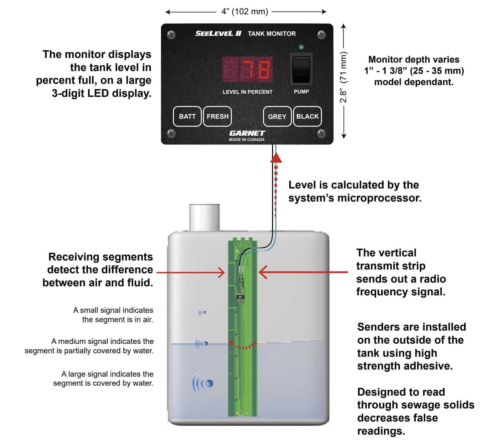
The illustration below describes how the SeeLevel monitoring system works. There is also this video.
What You’ll Need
- Note: we sell a complete kit with everything you need for this system in our store. As always, we appreciate your support.
- A SeeLevel 709-N2K-PM. It’s very important that you get the N2K (NMEA2000 version). There are some RV-C versions that can work with the Cerbo GX but, at the time we’re publishing this blog post, they prevent anything else from working on the VE.Can bus such as other Victron Energy components like the Lynx Smart BMS, etc. This product is the actual “panel” that looks like the one shown in the illustration above. It’s designed to mount onto a wall in your rig for checking the levels of your tanks. So, you can locate that in a convenient location or choose to “hide it away” next to your Cerbo GX if you only want to reference the Cerbo GX screen for tank levels. There is a newer product from SeeLevel that’s called the Soul which does not come with the panel and supports up to 7x tanks. However, the Soul cannot be sold to DIY customers – according to the manufacturer (Garnet) that is an “OEM-only” product. Also, it speaks “RV-C” over the CAN network instead of NMEA2000 which is a problem (see above).
- One or more sensors/senders. You’ll want one sensor per tank in your system with a maximum of 3x (fresh water, grey water and black water). For instance, if you only have a fresh and grey tank, you’ll likely only need two sensors. The sensors come in the following options:
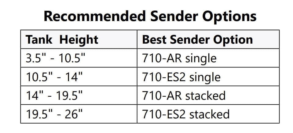
- The 710-ES2 sensor can monitor tanks between 5.5″ and 14″ tall
- The 710-AR sensor can monitor tanks between 3.5″ and 10.5″ tall
- If you have a very “tall” tank you can combine two sensors which is detailed in the manual and sender/sensor guide.
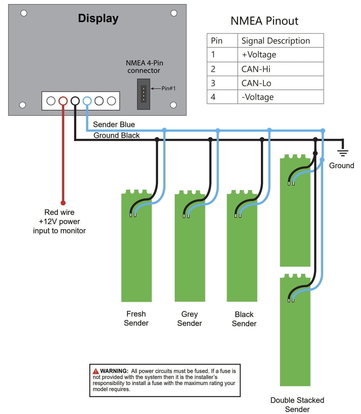
 A Victron Energy Cerbo GX with an open/available VE.Can port
- CAN data cable. See details on how to make this cable below. Parts you’ll need for to make this cable are listed below.
- A standard UTP/network cable with RJ45 connectors. The CAN connection for the Cerbo GX is on the back of that panel so the location of the panel (and the distance to the Cerbo GX in your system) will determine how long of a cable you need.
- A 120 Ohm resistor, 1/4 W, 5%.
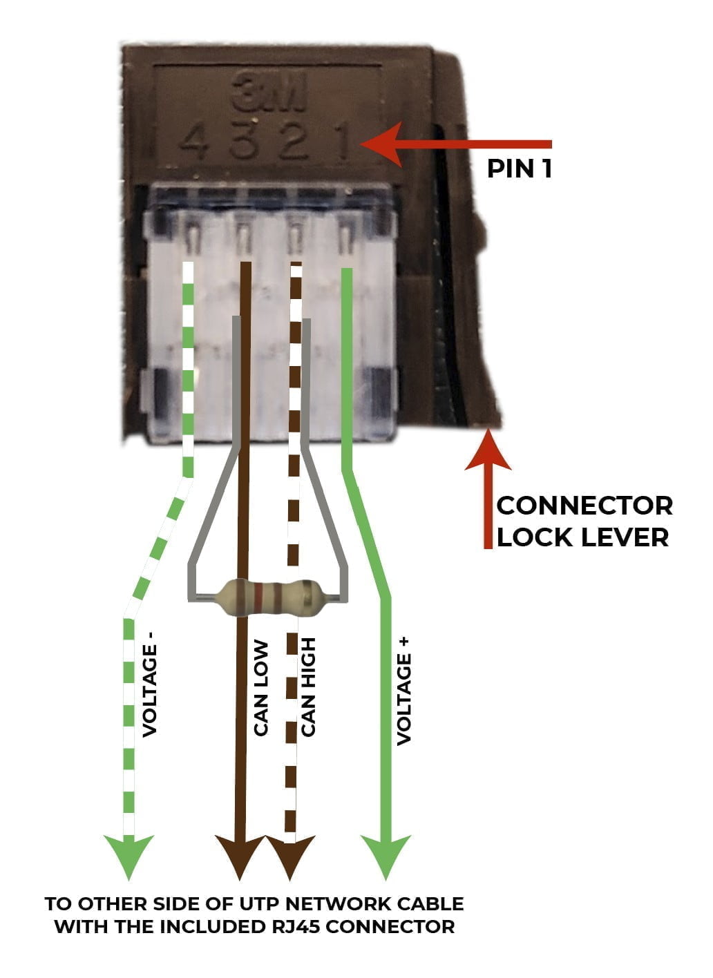
- 3M 37104, 4-pin connector. You should consider ordering a few extra of these since it’s kind of tricky to get all the wires into the connector without them pulling out.
 A
A Creating a NMEA2000 “Network”
Connecting the SeeLevel Panel to the Cerbo GX
If you happen to already have a NMEA2000 network in your rig you’ll approach this very differently. But, for the sake of this post, we’ll assume you don’t. So, we’ll be making a cable that connects the 4-pin connector on the back of the SeeLevel panel to a VE.Can port on the Cerbo GX in the form of a NMEA2000 (N2K) “network”. The parts you’ll need for this are detailed just above.
Note: we include a pre-made cable for this in our kit if you don’t want to mess with this yourself!
To start, cut off one of the RJ45 connectors from the UTP/network cable you’ll be using. Then strip away about an inch of the outer insulation from that end. You should see 4 “pairs” of wires twisted together (8x total wires). The “pairs” are various colors and each “pair” has a “solid” and a “striped” wire. You’ll want to identify the brown and green pairs – you will keep those and cut away the others (orange and blue pairs). There may also be some plastic material inside with the wires than can be removed.
At this point, you should have four remaining wires: brown solid, brown striped, green solid, and green striped. These will be wired up to the 3M 37104, 4-pin connector as shown in the illustration below. Untwist each of the 4x wires to separate them and then gently insert them into the correct location in the connector. Then, insert one end of the resistor into pin #2 and the other into pin #3. It can be tricky to get all these wires into the right “slots” and prevent them from pulling out. Take your time and only move onto the “crimping” step when you’re confident everything is aligned correctly. Now finish up the cable by crimping the connector. You can buy a special crimping tool to crimp this connector but we’ve found that a pair of pliers used to pinch the top of the connector down onto the bottom works fine.
Attaching Sensors and Wiring Them to Panel
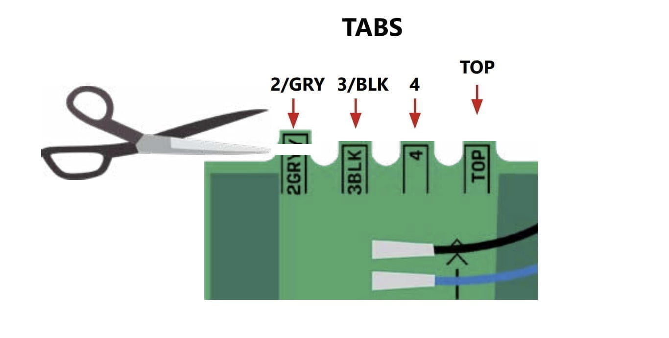
The first thing you’ll want to do is “program” each sensor so that it can be assigned to monitor a specific tank (fresh, grey, black). Typically this is as simple as cutting away the correct “tab” at the top of the sensor. For instance, if the sensor will be used to monitor a grey water tank, you would cut away the tab labeled GRY. For fresh water tanks, you leave the sensor as-is and don’t cut any of the tabs. If your tank is so tall that you need two sensors to cover its height, these tabs are also part of how you’d “program” which sensor is the “top” and which was the “bottom”. Finally, if you have more than one tank of a particular type (i.e.: more than one fresh water tank for example), these tabs enable you to differentiate those as well. All of this is detailed in the tank senders manual but the illustration below is a simplified version that is likely to apply to most van builders.
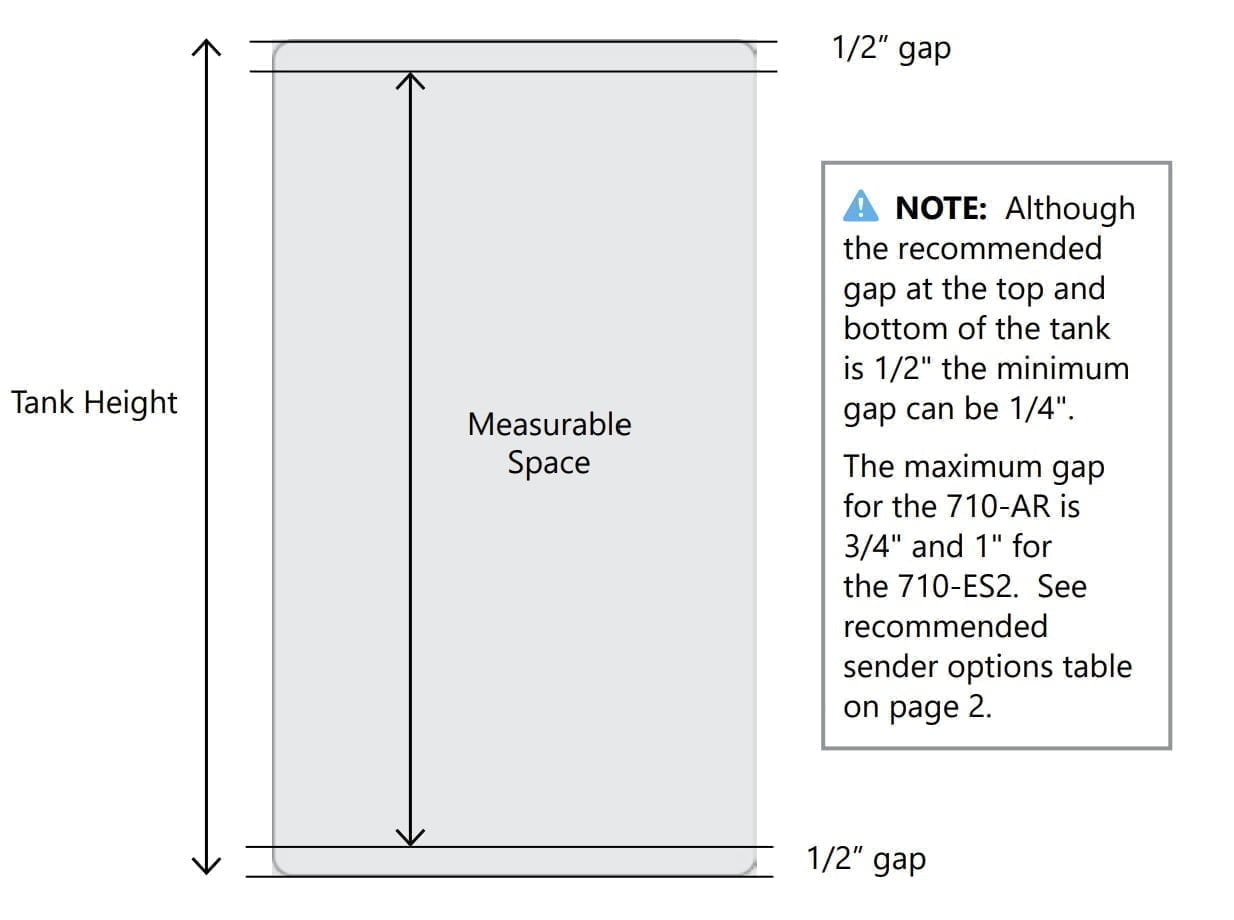
 Next, you’ll attach the sensor(s) to your tank(s). This is super easy. Just peel away the backing on the sensor and attach it to the tank with its adhesive strip. Be sure that you’ve cleaned the tank surface where you’ll be sticking the sensor. Ideally, you want about 1/2″ of space below the sensor on the bottom of the tank and 1/2″ of space above the sensor on the top of the tank.
 Be sure there are no metal objects near the sensor (within 3-5 inches). I once had a SeeLevel sensor reporting funky values and traced it back to a metal strap that was securing the tank. Moving the sensor a few inches away solved the problem.
If a sensor does not fit the full height of the tank, you can “justify” the sensor’s location to be either closer to the top or bottom, depending on the type of liquid. For fresh water tanks, it’s best to have them closer to the bottom since you’re typically most concerned about running out of fresh water, and for waste tanks (grey/black), you want them closer to the top since you don’t want to overfill those tanks. You can also pair two sensors together for particularly tall tanks as we mentioned above and as detailed in the manual.
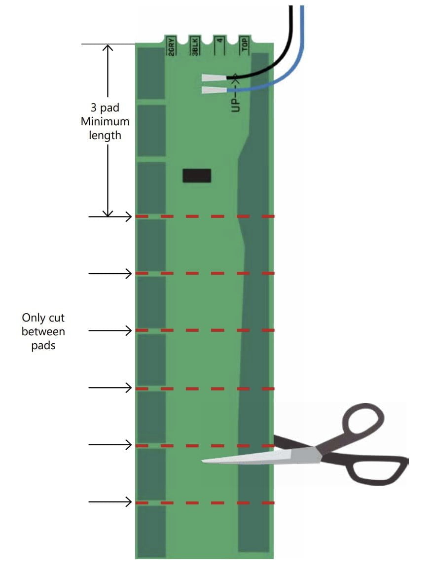
If a sensor is too tall, you can shorten it by cutting off a portion of its length. You simply cut the sensor at one of the spaces between the “pads”. Note that you must leave at least 3x pads at the top of the sensor. The top is where the wires are attached. This is all illustrated in the image below.
 If the tank is outside the rig, you can protect it from the weather by coating it with rubberized undercoating. SeeLevel specifically recommends 3M 03584 Professional Grade Rubberized Undercoating or Gravel Guard Rocker Guard Coating By Dominion Sure Seal. We’ve tested the 3M product and it works well. We tested another undercoating product from a local hardware store and it damaged the sensor!
Once the sensor(s) have been placed the wiring is also quite simple. There is a white connector included with the system that plugs into the white connection on the back of the panel. It has the following 3x bare wires.
- The red wire should be connected to a circuit-protected 12 volt DC positive supply (likely to your 12 volt load center).
- The black wire should be connected to your 12 volt DC negative supply (also likely your 12 volt load center). This one will be “split” to each sensor. We recommend a Wago, lever lock connectors for this.
- The blue wire is also split to each sensor.
- Each sensor has a short, blue, and black wire that can be extended to the required length with additional wire. All of the black wires should be tied together and all the blue wires should be tied together which is illustrated below.
Configuring the Sensors
At this point, you’ll want to power up the SeeLevel panel and go into the settings to configure each tank. The SeeLevel panel we’re discussing in this post (and that we sell in our store) can monitor the “standard” 3x tank types found in vans/RVs (fresh, grey, and black). If you don’t have all three types, you can simply connect and configure the ones you need. In other words, if you only have a fresh and grey tank, it will ignore the “black” (“waste”) tank. Each tank needs at least one sensor/sender but, as mentioned above, you can use 2x sensors/senders on taller tanks in order to cover the full height of the tank(s).
Using the Tank Menus
This is confusing and you’ll probably have to read it a few times and then fumble around as well. I tried to write it as clearly as I can but it’s just not intuitive!
To enter a specific tank’s menu, you press (and hold) the tank type and then simultaneously press the “batt” button. For instance, if you want to enter the black tank’s menu, press (and hold) the “black” button and then press (and hold) the “batt” button. Once you’re in the menu, the length of time you continue holding both buttons determines which option/setting you’ll be interacting with as follows. Releasing the two buttons selects that menu and, when you’re done interacting with the menu you press the “batt” button again to save and exit.
- Buttons held for 1 second: diagnostic information (diA shown on panel)
- Buttons held for 5 seconds: alarm options (ALr shown on panel)
- Buttons held for 10 seconds: connected sender/sensors (last two digits of r5 shown on panel)
- Buttons held for 15 seconds: tank capacity (last two digits of cA shown on panel)
First, disable any tank types that you don’t have. For instance, if you don’t have a black tank, remove it by entering that tank’s “connected sender/sensors” menu (a ten-second press, see above). Once in the menu, press the “fresh” button to cycle through the options:
- SE0 = no tanks of this type (use this to disable this type of tank)
- SE1 = a single tank of this type (use this to reenable this type of tank if you’re adding it)
- SE2 = two tanks of this type
Use the “batt” button to save and exit.
Next, configure the capacity of each of your tanks. For each tank, enter that tank’s “tank capacity” menu (a 15-second press, see above). Once in the menu, you’ll see a number that represents the tank’s capacity in gallons. Use the “fresh” button to increase the number and the “grey” button to decrease. Use the “batt” button to save and exit.
If you have already connected your SeeLevel panel to the Cerbo GX you’ll need to reboot it. Any changes to the SeeLevel configuration require a reboot of the Cerbo GX to be read correctly.
Configuring the Cerbo GX
Yay! It’s time to plug the SeeLevel panel into the Cerbo GX. The funky crimped side that you just made goes into the back of the SeeLevel and the RJ45 connector plugs into an available VE.Can port. Be sure to use a terminator in the unused VE.Can ports. They look like a connector without a cable (photo) and a few of them would have been included with your Cerbo GX.
I recommend rebooting the Cerbo GX at this point. When it comes online, you should see a few things changed. The tank(s) should appear on the touch screen “pages” and in the menu as shown below. Note that you should only see the tanks that have one or more sensors configured. In other words, if you followed our example earlier and disabled the black tank monitoring by setting the number of connected black tank sensors to zero, you should not see it appear on the Cerbo. If you do, you can revisit those settings.
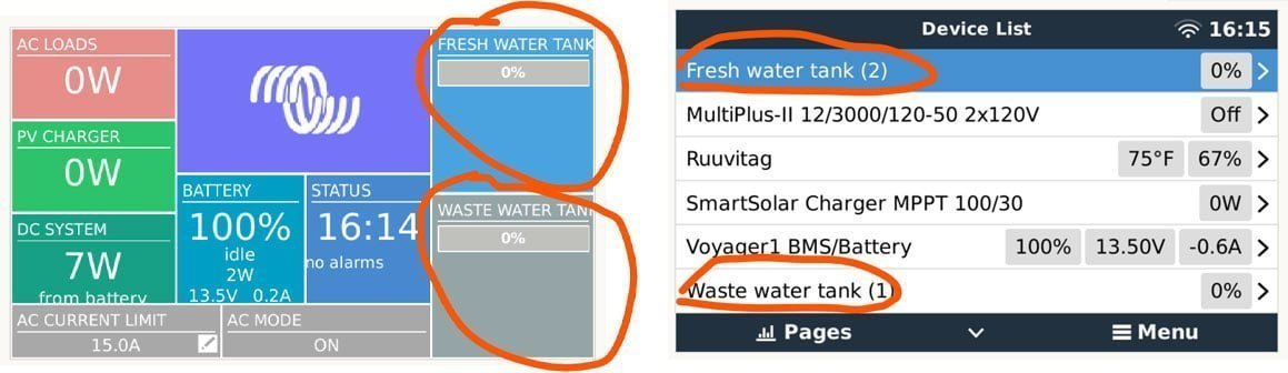
You can now enter the settings for each of the tank sensors by pressing on its name from the Cerbo GX menu this should show you more information about the tank and its status.
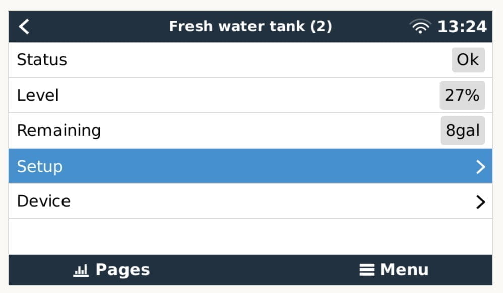
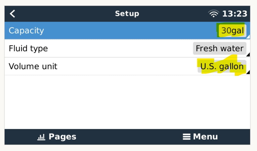
From there, if you press on “setup”, you see the tank’s capacity, fluid type, and volume unit as shown below. You can change the volume unit to gallons and then verify that what’s shown on the Cerbo GX matches the capacity you set when configuring the SeeLevel which is 30 gallons in our example image. Each “type” of tank that is enabled on the SeeLevel panel should come across on the Cerbo GX with a similar name: “fresh water”, “waste water” for grey tanks, and “black water (sewage)” for black tanks. As far as we can tell you cannot customize the name but you could use the “fluid type” menu on the Cerbo GX to change the label to something else.
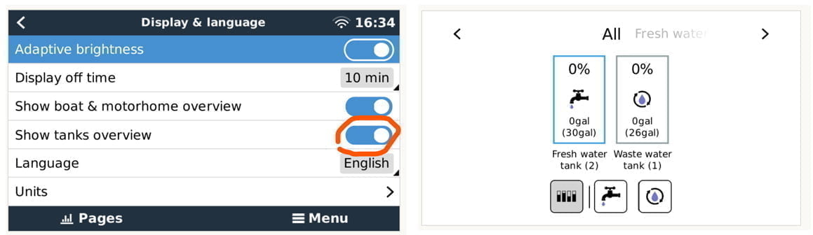
Finally, you may want to enable the “tanks overview” page/screen on the Cerbo GX that is shown on the right side of the image below. To do so, enter the menu on the Cerbo GX, navigate to “settings” and then “display & language”. This is shown on the left side of the image below.