

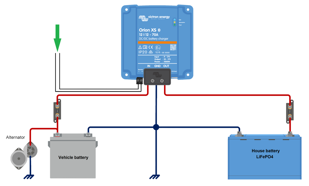
It’s important that your DC-DC chargers turn on & off with your engine to prevent depleting your vehicle starter battery. Victron Orion XS DC-DC chargers include Engine shutdown detection and Input voltage lock-out features to help ensure that your charger is only on when the engine is running and your primary alternator is producing current to charge your house Lithium battery bank. This blog touches on the configuration options for the Orion XS 50, XS 70, & XS 1400 and provides some wiring alternatives for dedicated wiring control of your DC-DC chargers.
Ready to skip right to the wiring alternatives? Follow these links:
- Using a fuse tap
- ProMaster Upfitter Interface Connector
- Sprinter Upfitter Connector
- Transit Vehicle Interface Connector
- Adding a manual switch
Victron added an emergency reverse charge function to the Orion XS DC-DC chargers. If your start battery is depleted for some reason (not due to your DC-DC charger after reading this blog!), you can now use your house battery bank to charge your vehicle battery bank. Check it out.
What Orion XS Configuration Settings Should I Use?
To make your Orion XS turn on & off with the engine, we recommend enabling Engine shutdown detection in modern vans. Start with the default parameters, as those defaults work for most customers.
Check your Orion XS DC-DC charger settings using Bluetooth and the VictronConnect app. If you have a Cerbo GX and are using the VRM (highly recommended!), you can also configure your devices through the VRM.
After connecting with your Orion XS using VictronConnect, open the Settings menu using the cog in the upper right corner. You will see two important sections that help control when your charger is enabled, Engine shutdown detection and Input voltage lock-out.

Make sure that Engine shutdown detection is enabled. Set the Alternator type to Smart Alternator for most modern vans, including Mercedes Sprinters and Ford Transits. Ram ProMaster is the exception, where variable voltage is not used and the Regulator Alternator setting in Orion XS chargers is the best fit.

Also make sure that Input voltage lock-out is enabled.

We recommend starting with the default values for the Engine shutdown detection and Input voltage lock-out settings in 12 Volt systems. Turn your van on & off, and drive your rig under varying conditions. Keep checking your charger to verify that it’s on & off when you expect it to be.
For 24 Volt house battery systems, the Victron Orion XS 1400 DC-DC charger defaults may not have the correct voltages. In most rigs, settings should be changed to 12 Volt values for the Engine shutdown detection and Input voltage lock-out settings.
Using the Why is the charger Off? Feature
Did you notice the Why is the charger off? feature on the main page of your Orion XS DC-DC charger? Victron provides this very handy troubleshooting tool for troubleshooting your Engine shutdown detection and Input voltage lock-out settings. Just tap on that feature, and Victron will tell you exactly why your Orion XS is disabled. Use that information to adjust settings as necessary.

If you’re expecting your charger to be on, the Why is the charger off? notifications tell you exactly what to change. The main causes you might see include the following:
- Engine shutdown detected: Check your Engine shutdown detection and Alternator type settings.
- Low input voltage: Check your Input voltage lock-out settings.
- Disabled by remote or BMS: Check your remote on/off terminal wiring (more on this in the next section!). If your system uses DVCC for External Control of your charging sources, your Orion XS might be disabled because your BMS turned your DC-DC off. Check your BMS status for more information.

Wiring Examples for On/Off Control
If the Engine shutdown detection and Input voltage lock-out features work well for your chargers, you’re done. Skip this section, or go ahead and read on for more options. These wiring alternatives provide direct D+ signal “engine running” control over your chargers. These wiring examples can be used to supplement the DC-DC charger power wiring shown in our free example wiring diagrams.
Unfortunately, there are many variations in how camper van engines and alternators perform. We can’t offer you a Use these settings easy button if your charger isn’t turning on and off when you need it too. If the charger features aren’t working for your rig, or if you just don’t like twiddling configuration settings, these remote on/off wiring solutions can work for you.
Traditional engines have a D+ signal that provides 12 Volts when the alternator is producing current. The D+ signal is disabled when the alternator (and the engine) are off. The D+ signal allows an easy way to control DC-DC chargers to be enabled only when the engine is running.
Victron Orion XS DC-DC chargers have a small remote on/off terminal block. The Orion XS devices come from the factory with a small jumper wire that enables the charger. Whether you use a fuse tap or the vehicle-specific example wiring examples that follow below, you will remove the jumper wire and connect a control signal to the Orion XS remote on/off terminal connections.

The Orion XS remote on/off terminal connections give you flexibility in how you can control your DC-DC charger. The remote on/off terminal connections work in conjunction with the Engine shutdown detection and Input voltage lock-out settings, so if any one condition is not satisfied your DC-DC charger will remain off.
-
a) L-H pin wiring means that connecting the L- and H-pins can enable the charger
-
b) H-pin wiring means that providing a positive voltage signal to the H-pin can enable the charger
-
c) L-pin wiring means that providing a grounded signal to the L-pin can enable the charger
-
d) BMS control via H-pin is just a fancier version of b) H-pin wiring, where some intelligent source (such as a BMS with an Allow To Charge signal) provides positive voltage to the H pin to enable the charger
The factory remote on/off jumper is an example of a) L-H pin wiring, except Victron skipped the switch and always connects the L & H pins of the remote on/off connector together. This is the simplest solution if the default Engine shutdown detection and Input voltage lock-out settings work for your camper.
Fuse Tap
So how do you find the D+ signal? One easy way is to add a fuse tap to an existing fused circuit in your vehicle. Fuse taps are also called add-a-circuits or piggyback fuses. These devices tap in to existing ATC fuses, adding an additional fused circuit. A fuse tap has a location for re-installing the existing fuse plus adding a second ATC fuse for a new fused connection. The key is to understand your van’s interior fuse box(es). By reading the Owner’s Manual (yikes!, did I go there?) or using a multimeter to check circuits when the van is on & off, you can identify an existing circuit that behaves like the D+ signal. This may be an inverter control circuit or accessory power in some vehicles. Be careful that the circuit really is “engine running” and not ignition, auxiliary, or key modes, because you really need the alternator to be providing power and you do not want your chargers on in key mode without your engine running.
Fuse tap circuits will use the remote on/off connections example of b) H pin wiring. The fuse tap uses a signal emulating the D+ signal where 12 Volts is present only when the engine is running. Connect the fuse tap circuit to the Orion XS H-pin.

Fuse taps may interfere with the fuse box cover. Maybe you found a circuit, but it’s behind the passenger glove compartment and not in an easily accessible location like the driver’s seat pedestal. Many vans provide control signals that don’t exactly match the behavior of the D+ signal. You were promised precise on/off control of your DC-DC charger, so read the next few sections for specific wiring advice for your rig.
Ram ProMaster Orion XS Wiring (Upfit Interface Connector LSD)
Ram ProMasters with the Upfit Interface Connector have access to the Auxiliary Run Relay Control (LSD) signal, which is pulled to ground when the engine is running. That means the LSD signal is the opposite of the D+ signal, but that’s okay because the Orion XS remote on/off connections are flexible and can work with active-low logic too.
This ProMaster Forum thread consolidates all of the Upfit Interface Connector guides into one handy place. You will need a Tyco 1-480710-0 mating connector and Tyco 350218-1 terminals to use with the Upfit Interface Connector that is located in the passenger B pillar. LSD is on Pin 2 of the mating connector. Connect LSD to the L-pin remote on/off connections following example c) L pin wiring.

Mercedes Sprinter Orion XS Wiring (Upfitter Connector EK1 D+)
Mercedes Sprinters with the Upfitter Connector have a D+ signal easily accessible in the driver’s seat pedestal. The D+ signal is on the EK1 terminal strip.
Mercedes Body and Equipment Guidelines (BEG) describe the D+ signal. Terminal strip EK1 Pin 1 contains the D+ signal, and D+ connects to the H-pin using the remote on/off connections example of b) H pin wiring.

Ford Transit Orion XS Wiring (Vehicle Interface Connector C33-E Engine Run)
Ford provides a Vehicle Interface Connector with an Engine Run (Ground) signal similar to the ProMaster LSD signal. Engine Run (Ground) is pulled to ground when the engine is running, so it’s the opposite behavior as a D+ signal. The Vehicle Interface Connector C33-E is located inside the driver’s seat pedestal.
The specific C33-E connector and pinout varies with model year, however every Transit has a Vehicle Interface Connector - it’s not an order option. Prior to 2020, C33-E is a six pin connector with this mating harness or an eight pin connector that comes with the mating connector yet requires terminals. From 2020 to 2025, C33-E is a ten pin connector with this mating harness. From 2026 onward, C33-E is a 12 pin connector with this mating connector and terminals.
Engine Run is on Pin 3 of the six pin harness and Pin 2 of all the larger C33-E Vehicle Interface Connectors. Connect Engine Run to the L-pin remote on/off connections following example c) L pin wiring.

Be aware that Ford’s Body and Equipment and Mounting Manual (BEMM) cautions that “Load-shedding with Battery SOC Protection switched ground signal is a signal that must always be the primary controlling signal to be used to handle third party loads totalling over 60A”. What this means is that the Ford Engine Run signal alone should not be used for the XS 70 or multiple XS 50 or XS 1400 units in parallel. In that case, adding a Bosch automotive-style normally open relay is advised to incorporate the Load Shed signal. The following diagram uses Engine Run (Pin 2) and Ignition (Pin 6) to control the relay contact, and the Load Shed (Pin 4) signal is a switched ground that connects Engine Run to the L-pin remote on/off connections following example c) L pin wiring.

Example with Manual Switch
A manual switch can be added inline with the jumper, fuse tap, or vehicle specific wiring to provide you with additional control of your DC-DC charger. You may want the capability to turn your charger off, for instance if you’re not boondocking or just driving your van around town.
A Single Pole Single Throw (SPST) switch is ideal for this application. A Contura SPST On-Off Switch can be wired to replace the jumper and use the remote on/off connections example of a) L-H pin wiring.

Alternatively, the SPST switch can be placed inline with the single wire connections from the fuse tap and vehicle-specific examples above. When the SPST is on (switch closed), the “engine running” signal will turn the Orion XS on & off with the engine. When the SPST is off (switch open), your charger will be forced off.
Resources
Ready for a full electrical system that includes a DC-DC charger? Check out our electrical bundles.
Victron Orion XS DC-DC chargers
Still confused about how to best use your DC-DC charger? We are always happy to help, so please contact us.
Frequently Asked Questions
How does a DC to DC charger work?
A DC-DC charger takes excess current from your vehicle’s alternator and uses that to charge your house battery bank using a charging profile optimized for your batteries. DC-DC chargers provide battery isolation & controls to ensure that your starter battery is not drained.
Should I connect a DC-DC charger to the battery or the alternator?
Your vehicle’s battery and alternator work together to provide stabilized voltage and safe system operation. Connect a DC-DC charger to the battery or the Customer Connection Point (CCP), if present on your vehicle. The CCP is a manufacturer’s intended location to integrate customer power systems with the van’s house battery system.
How many amps does a DC-DC charger draw?
DC-DC charger amperage varies by model, with 50 Amps or more being a typical value on modern DC-DC chargers. Multiple units can be combined in parallel for increased charging draw. Keep in mind that most manufacturers recommend not exceeding 50% of the rated capacity of your vehicle’s alternator.
Do I need a DC-DC charger?
Yes, especially if your house battery bank contains Lithium (LiFePO4) batteries. A DC-DC charger provides battery isolation and a proper charging profile for your house battery bank.
Why should I double-check that my DC-DC charger is off when the engine is off?
Check that your DC-DC charger turns off when the engine is off to prevent draining the vehicle starter battery.
What are the differences between the XS 50, XS 70, and XS 1400?
Victron Orion XS 50 and XS 70 DC-DC chargers are intended for 12 V systems. The XS 1400 DC-DC supports mixed voltage systems, such as 12 V vehicle batteries and 24 V house batteries. The XS 70 is a 1000 Watt charger, while XS 50 and XS 1400 (in mixed voltage systems) are 700 Watt chargers.
Additional Resources
Victron Orion XS DC-DC Battery Charger datasheets and manuals
Recent model year RAM ProMaster Body Builder's Guide (BBG) has been put behind a paywall. At this time, 2020 information is at https://www.ramtruck.ca/en/body-builder/guide/year/2020/nameplate/promaster
Mercedes Sprinter Body and Equipment Guidelines (BEG) https://www.mbvans.com/en/upfitter/tech-info/beg
Ford Body and Equipment Mounting Manual (BEMM) https://www.fordpro.com/en-us/upfit/publications/


