If you’re building a camper van electrical system, or planning your vanlife power setup, the first power-up is a big milestone. This blog is Part II of a two-part series on powering up your camper van electrical system for the first time. Part I discusses steps to think about before or during your build, and Part II focuses on the steps to energize & configure your mobile power system. To be honest, planning for & commissioning your electrical system is a process, so if you missed Part I, give it a read first before diving in here.
This blog hopes to provide some of the why to go along with the what when commissioning your electrical system.
Your build is progressing, and you're almost ready to Turn. It. On. Does it feel a bit daunting? Turning your electrical system on for the first time can be as exciting as putting that first hole in your new rig. How many times did you measure before you cut? Working methodically to power your system on is the same idea! It's going to be okay, and here is a checklist for getting your system up and running.
Every system is different, and you can find a bunch of different how-tos on the interwebs. Some manufacturers provide commissioning steps in their manuals too, as an example this procedure is a good list even if you don't have a Victron BMS. You did read the manuals for your equipment, right?
Here’s our take on a solid approach to getting your electrical system up and running.
Double check
At long last, can we finally get on with the steps? Yes, of course, as long as you consider checking your connections as part of the turn up sequence. Incorrect wiring can cause damage. This section is called double check, but we really mean triple check.
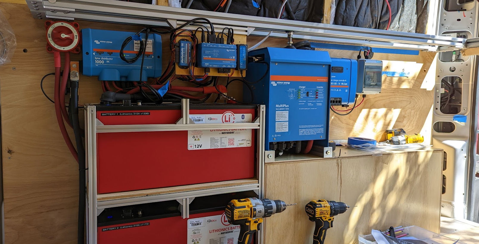
Step 1 - Test Your Lugs, Terminals & Ferrules
Check that your lugs and ferrules are done properly. You are not trying to treat those connections with "kid gloves" either. If you can yank on a lug and it comes off, that's not good! You're relying on those connections to handle high currents and keep you safe. Lugs, ferrules and terminals should be secure and difficult if not impossible to remove with a simple pull.
Let’s briefly touch on ferrules too, which can be new or difficult for some customers. Since tinned, stranded wire from brands like Ancor is preferred for environmental & vibration tolerance (e.g. your safety!) in mobile power systems, wire ends for screw terminal connections should use a ferrule. Generally, a hex ratcheting ferrule tool is preferred, as the round shape formed after the crimp fits best in most screw & spring clamp terminals. In some cases, for instance with the Orion XS DC-DC chargers using the recommended 6 AWG wire in our free example wiring diagrams, only a hex crimped ferrule will fit (and a square crimped ferrule will not due to the resulting shape). The Victron Multiplus II inverter/charger AC terminal blocks require 18 mm bootlace ferrules that are longer than what is provided in most ferrule kits, and using shorter ferrules may cause the terminal block spring clamps to come loose. Do yourself a favor and use the correct ferrules, even if you need to go replace a few connections before powering on your system. Part of double checking can include learning that a few minor changes can go a long way to improving the safety and reliability of your system.
Step 2 - Properly Tighten Your Connections
Not only do your connectors need to be done properly, but those connections must be tightened properly. Properly means that you're not a tire jockey tightening nuts with your air wrench! Whether it's Victron, Blue Sea, or any other manufacturer, your device manual provides torque specifications for the connections. So, please use a torque wrench!
Step 3 - Review Every Connection in Your Wiring Diagram
Review your wiring diagram. Review our complete set of example wiring diagrams. Depending on your system, you may use sections from more than one diagram. We recommend printing out your diagram(s), then highlight each wire & connection as you go through the double check on your system. While you're in the diagram, you did note all of the case & chassis case grounds, right? These safety connections are not optional. Check your MPPT case ground, your Multiplus PE connection, and of course your vehicle chassis ground connection.
Step 4 - Check Your Fuses & Breakers
Are all your fuses and safety devices installed? Remember that a fuse is sized to protect the wire. Double check that the correct fuse rating is installed in every location. Check your circuit breaker sizes too, and since we're almost ready to turn things on, go ahead and flip those breakers to the off position for now. Here's a quick tip for the Lynx Distributor: if you're not using every Mega fuse position in the Distributor, the LED will remain orange and not a happy green. With a Lynx Shunt or Lynx BMS connected to a Lynx Distributor, an empty Mega fuse slot will show up as an alarm because a blown fuse (i.e. an open fuse) looks no different than a missing fuse. We recommend mounting spare fuses in your unused Mega fuse slots. Hopefully you'll never need them, but maybe you'll be glad to have one handy in the future.
Step 5 - Test Wiring with a Multimeter
Use a multimeter to triple check those connections. Just to be clear, we're doing all of these checks before the system is energized! Check each load branch wiring for no "dead shorts", where the power and ground wires should show resistance and not be shorted together. Same for the AC wiring, where the hot and neutral should not be shorted. (Keep in mind that a Multiplus inverter/charger contains a ground relay that automatically connects neutral to the chassis ground if no AC input is supplied, so those AC wires may read as shorted.)
Step 6 - Wrap It Up
As you are wrapping up your double checks, it’s a good time to cover any exposed terminals to prevent damage from any accidental tool drop. Dress your cables with cable ties to minimize vibration and torque on equipment connections.
Checklist for your wires and safety devices
Test & inspect that you properly crimped your lugs, terminals, and ferrules
Check that your connections are torqued to manufacturer specifications
Review your wiring diagram and mark off that all wiring connections are as intended
Check that your fuses & breakers are sized properly
Test wiring for shorts & opens using a multimeter
Install cable housings and cover any exposed terminals
Finally!
This is the moment where it all comes together. Start will all equipment switches turned off. Make sure the master battery switch or contactor in your BMS is off. If needed, temporarily remove fuses to keep sources and loads un-powered. Make sure your Multiplus inverter/charger switch is in the off position.
As a reminder from Part I, we’re presuming that your batteries are fully charged before reaching this step.
Work methodically! If something doesn't look right as you go through the steps, stop and assess. It's okay to power down, make a fix, and start over. And if you listened to our guidance for working on a testbed prior to a full camper van system, do as many steps as feasible...then get back to testing & building that rig!
Here is our recommended turn-on procedure:
1) If your batteries have an on/off switch, go ahead and turn them on. If your system has a BMV-712, check your battery bank voltage now. Also check your battery using the manufacturer’s app if it has Bluetooth support. You’re looking to confirm that the batteries have no alarms and show very similar voltage readings. This tells you that your battery bank is successfully connected and ready to serve as an energy source for your system.
2) Turn the master switch or contactor on. Use a multimeter and check the voltage on your Lynx Distributor, it should (nearly) match your charged battery voltage. Use the battery and/or BMS app to check the battery voltage, current (should be a low number), and status. If you haven't already, make sure your battery BMS firmware is up to date.
Some customers with a Victron BMS may run into a snag here and notice a pre-charge error. The BMS can be sensitive to capacitance and loads, particularly in complex systems with a Multiplus inverter/charger, a secondary alternator, or many other connections on the Lynx Distributor. If you get a pre-charge error, first check for real problems such as a short or incorrect connection on the distribution. If the connections are okay, you may need a simple workaround to sidestep the pre-charge error. One method is to enable one of your charging sources (see Step 4) to power-on the distribution side of the BMS before enabling the BMS contactor. This workaround pre-charges the distribution with a source other than the batteries through the BMS, therefore the BMS will correctly finish its turn-on sequence with no errors. Most customers can leave their system in on or standby modes after the commissioning steps are complete, so the pre-charge workaround is just a temporary annoyance.
3) If you have a Cerbo GX, it should be powered-up through your distribution. On your touch screen or app, check your Devices list and make sure your battery monitor is reading properly. This confirms that your shunt connection (either VE.Direct to a SmartShunt or CAN to a BMS) is correctly done. If your batteries have "Victron communications", also check your Cerbo Devices list to verify that your battery(ies) are present. You may need to change the CAN bus profile setting in your Cerbo GX to match your batteries and get Victron communications established.
3plus) Give your Cerbo GX some internet access! This step helps provide troubleshooting information for all the subsequent steps and makes it easy for you (and easy for us to help you). Ultimately, get access to your electrical system using the VRM as discussed in this blog. Using the touchscreen, connect to a WiFi network and set up the VRM. Make sure your Cerbo has the latest firmware.
4) Turn on charging sources one at a time. The order of charging sources to enable is not critical, but we suggest prioritizing the Multiplus inverter/charger, solar, DC-DC charger(s), then the secondary alternator kit. For each charging source, use the following steps:
- Check your battery monitor. Charging current should increase (and be a positive value) when the charging source is on.
- Check your Cerbo Devices list to make sure the device is communicating with your system.
- Update the firmware. Check and/or update the configuration to match manufacturer specifications.
- Periodically check your cables by hand or with a thermal imager. When charging heavily, some cables may be warm to the touch but not crazy hot.
After checking one charging source, turn that source off and iterate on a different charging source. Keep it simple and methodical to safely check each part of your system. Once you've individually checked out each charging source, then you're ready to turn on multiple charging sources.
There are some things to watch out for when turning on your charging sources.
-
Apply battery power and turn on your Multiplus before connecting shore power. Here are some tips for programming your Multiplus.
- Charger settings: The devices do not come preconfigured for lithium batteries, so change that charge profile!
- Inverter settings: We recommend that the low voltage shutdown thresholds are set slightly higher than your BMS low voltage disconnect value. The inverter should turn off before completely discharging the battery bank, which could turn off your entire system.
- General settings: The default AC input current limit is 50 Amps, which is too high for most DIY garages & driveways using a standard 15 Amp household receptacle. Set that current limit before applying shore power, and let's not pop your circuit breaker or potentially damage your shiny new Multiplus, please?!
- We touched on solar in this blog. Your Victron MPPT PV (photovoltaic) voltage must be 5 Volts higher than your battery voltage for a charge cycle to start.
- Check that your alternator-based charging sources turn off when the engine is off but turn on when the engine is on. You want to ensure that your camper van starter batteries are not depleted by leaving a DC-DC charger on with the engine off. Our Victron & Sterling DC-DC chargers can be configured to detect voltages, detect vibration, and/or utilize external "remote" on/off connections to keep your van's two battery systems properly isolated.
- VictronConnect tip: After connecting to a MPPT or DC-DC converter via Bluetooth using the VictronConnect app, if your device is powered on but in the off state (i.e. not charging), you will see a Why is the charger off? line on the status page. Victron tells you the reason your device isn't charging, and that can be pretty handy!
- Even with your battery switch or BMS contactor open, any charging source that is enabled will energize your Lynx Distributor. Why? Because your charging sources and your loads are interconnected on your distributor. Your master battery switch or BMS contactor separates energy stored in your battery bank from the distributor but does not disconnect the other sources of power. Be cautious while testing or doing maintenance, and make sure that all batteries and charge sources are off when required.
- DVCC tip: DVCC is an algorithm running in your Cerbo that intelligently coordinates your smart charging sources to provide only the charging current desired by your batteries & BMS. It's not quite magic, but testing with DVCC enabled can yield confusing results. Typically, if your batteries are mostly full (above the SoC threshold, State of Charge in your battery monitor), then your charging source(s) may be throttled to optimize battery lifecycles. Don't panic if your DC-DC charger doesn't put out a full 50 Amps in that case. Another source of throttling is heat, so testing mid-summer in high ambient temperatures may limit charging performance. You may need to move on to the next step, enabling loads to discharge your battery bank with charging sources off, then return to re-examine your charging performance with a lower battery SoC.
Need troubleshooting help? Don’t forget the cutting it in half approach as discussed in Part I. Our tech support team has tons of vanlife experience, so we’re here to help too.
5) Turn on loads one by one. Work through your checklist of all AC and DC loads. For each load, check with a voltmeter and look at your battery monitor or touch screen display. You should see an appropriate increase in AC or DC Wattage for each load. If your load reporting looks incorrect, double check your cabling, especially the chassis ground. Only the battery cables should be on the Battery Minus terminal of your BMS & shunt, and every other connection (like chassis ground!) should be on the distributor side. As with your charging sources, inspect your distribution and load cables & connections for excessive heat.
6) Check your battery monitor (i.e. shunt). Now that you can comfortably charge and discharge your batteries, make sure that your battery monitor is properly configured. In Victron-speak, you want to allow a successful synchronization so that the battery monitor correctly reports your SoC. After the first power up, the battery monitor may not show the correct SOC. To reach a synchronization (which can be checked using the VictronConnect app under History), first discharge the batteries to around 50% SoC using your loads, then turn off your loads and charge the batteries to 100% using a charging source (such as shore power which typically provides the fastest charging). Allow your system to complete a full lithium charging profile, transitioning from absorption (higher, constant current) to float (low current, constant voltage). If your battery monitor reports 100% SoC and shows a synchronization event, your battery monitor is properly configured and will provide correct SoC reporting. This step also ensures that any paralleled batteries in your battery bank are balanced, promoting equal sharing of the charging sources and loads from your batteries to prolong battery lifecycles.
7) Use your system and enjoy! Take advantage of the VictronConnect app and VRM to monitor your system performance.
While this blog is about turning on your system for the first time, many customers are already thinking ahead about maintenance & battery storage. Self-discharge of lithium batteries is quite low, so typically we recommend that you don’t need to completely turn off your system when not in use. If you have internet access and are using the VRM, then leaving your system on and idle is quite helpful for remotely checking in on your rig. You may find it handy to turn your Multiplus inverter/charger to Charger mode, which disables the inverter and saves you the 20-30 Watts of idle power from being constantly consumed while you’re not using your system.
To maximize your battery lifecycles, it’s recommended that lithium batteries are stored between 50%-70% SoC. Most importantly, lithium batteries have improved lifecycles when not exposed to high currents near 100% SoC. In other words, don’t leave your system plugged into a charging source constantly with your batteries at 100% SoC.
If you have a system with Victron NG or Smart batteries with DVCC enabled, the good news is that your system is automatically being optimized and you don’t need to take any special storage precautions. Victron automatically keeps the SoC optimized while allowing charging to 100% once per month, which keeps the battery cells balanced. For more basic or value battery-based systems, you may need to be a little more mindful about lithium battery storage. You may wish to manually enable/disable charging sources to manage your battery SoC. If you can store your electrical system with shore power, an alternative is to adjust your configuration profile to a lower absorption voltage that will limit charging to around 70%. Don’t forget that you need to charge up to 100% every month or so to keep those battery cells balanced. Change your system configuration into normal mode to allow charging up to 100%, then return to a storage mode configuration until you’re ready to use that rig. Don’t forget to change back to normal mode to get the most performance out of your electrical system while you’re on that trip!
Super-condensed power-on checklist
Start will all loads and charging sources off
Pre-charge your batteries and make parallel connections before turning batteries or battery switch on
At each step of your power-on, use your device’s Bluetooth app and a multimeter to check status & power. Also check for excessive cable heating
Use your battery monitor to check battery voltage, status, and current
Update firmware on each device as you go
If applicable, use your Cerbo to check that device communications are established. Set up your Cerbo VRM for remote monitoring and troubleshooting
Turn on charging sources one at a time. Test each charging source by itself before using multiple charging sources together
Turn on loads one at a time
After checking your charging sources and loads, take your system through several discharge then charge cycles to balance your batteries and synchronize your battery monitor
Don’t forget that storing & maintaining your batteries should be done at a lower State of Charge than your typical 100% pre-trip SoC
Summary
Successfully powering up your camper van electrical system for the first time is all about being methodical. There are four major steps in planning for & commissioning your system:
- Prepare your batteries
- Get familiar with your system with bench testing & incremental building
- Double check your wiring and connections
- Power up your batteries, charging sources, and loads in an orderly fashion, checking for voltage & heat at each step. Configure each device as you go.
FAQ: Commissioning & Configuring Your Camper Van Electrical System
-
What should I check before powering up my electrical system?
Inspect every lug and ferrule, check torque specs, confirm correct fuse ratings, and use a multimeter to ensure there are no shorts between positive and negative wires. -
How do I safely turn on my camper van electrical system for the first time?
Start with all switches off. Confirm battery charge and all connections before powering up. Power on your batteries then the master switch. Verify voltage before enabling charging sources or loads. -
How do I configure my Victron Multiplus inverter/charger for lithium batteries?
Use the Victron VEConfigure software to change the charge profile to lithium, set inverter low-voltage shutdown slightly above your BMS cutoff, and reduce the AC input current limit to suit your shore-power source. -
What recommended order should I turn on my charging sources?
Start with the Multiplus inverter/charger, then solar MPPT, DC-DC chargers, and finally any secondary alternator kit. Test one at a time before enabling them together. -
Why is my Victron BMS showing a pre-charge error?
This can happen when capacitance or load prevents proper pre-charge. First check that there are no shorts on your Lynx Distributor. Enable one charging source to energize the distribution side before closing the BMS contactor, then retry. -
How do I synchronize my Victron battery monitor (BMV-712 / SmartShunt / Lynx Shunt / BMS)?
Make sure to use a lithium-ion charging profile on your charger. Discharge batteries to ~50% SoC, then fully recharge until absorption transitions to float. Once the monitor shows 100% SoC and logs a “synchronization” event, calibration is complete. This can take some time, so be patient. - How should I store lithium batteries in my camper van?
Keep between 50–70 % SoC, avoid continuous charging at 100 %, and store in moderate temperatures. Systems with DVCC or Victron Smart / NG BMS manage this automatically.


