Introduction
Well, it’s summer in Florida, so what better time to dive into the world of air conditioning for your van? In this blog post, we’re going to take an in-depth look at installing the Mabru 12000 BTU rooftop, 12-volt DC air conditioner. We chose this unit for its quiet operation, energy efficiency, and overall value. I have one in my personal van, and it keeps me cool even in the Sunshine State’s scorching heat. We’ll also discuss how to modify the unit to fit a standard 14-inch by 14-inch hole, just as I did in my own van. You can find this unit for sale in our store, and as always, you’ll discover a wealth of information on our website at vanlifeoutfitters.com, including a handy spreadsheet comparing various 12-volt rooftop AC units on the market.
Before we dive into the installation process, let’s first discuss the tools and materials you’ll need
- Jigsaw (or your preferred tool for cutting the roof opening)
- Metric socket set/wrench
- ½” drill bit and a step bit
- Caulking gun and sealant (we recommend Loctite Marine PL or similar)
- Small zip ties
- Plastic bag or plastic sheeting
- File
- Rustoleum paint (or similar) to protect bare metal
- “Solar entry gland” for passing the wiring harness into the van roof (and grommet)
- Roof adapter, butyl tape, or PVC shims (if needed to fill in roof corrugations)
- Lap sealant (such as Dicor, if needed)
Let’s start by unpacking the contents of the Mabru AC unit’s box and understanding what you’ll use and what you might not need
- Paper roof-cutting template
- Manual (though we’ll provide you with a more detailed guide)
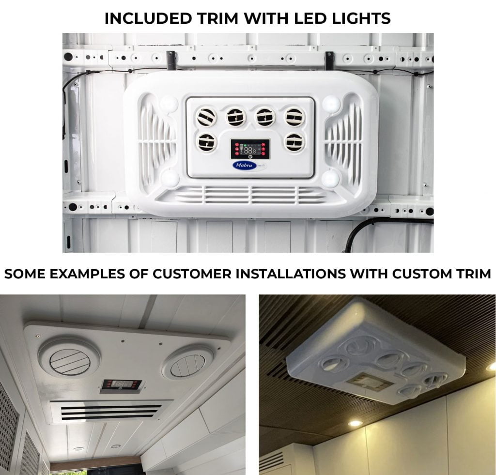
- Bag with 15mm nuts and LED lights (for fastening the unit with brackets and optional interior lighting)
- 6x mounting bracket pieces (for unit installation)
- Bag with the remote control and wires for optional LED lights
- Bag with rubber spacers (not used in standard installation), large black screws (for flanges on installation brackets), wire ties and mounts (for wiring harness routing)
- Plastic “L-bracket” things (not used in standard installation)
- The Mabru AC unit itself
- Note that the video shows some hoses at around 29 seconds. These are no longer included. They were for routing the condensation from the base plate to somewhere else – perhaps to use that water for another purpose. You can see the “ports” on the baseplate where the condensation drains onto the roof where those hoses, or something equivalent could be connected. Turns out no customers used them so they omitted them from the box.
The video below shows all the items in the box in the same order as the list below…
Finding the serial number
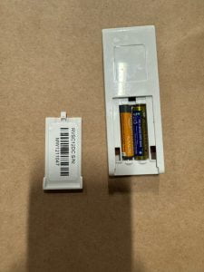
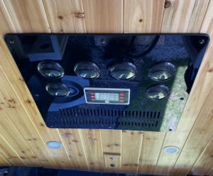
Before we dive into the installation, it’s wise to locate and make a note of the unit’s serial number for future support or repair needs. Starting in the summer of 2024, the serial number for the units is located inside the RV cover. Prior to that it had been in a different spots including behind the interior vent panel inside the return air compartment (example photo). On newer versions, you can also find the serial number inside the remote battery cover as shown in the photo.
Step 1: Finding a suitable location & cut opening
Begin by finding a suitable location for the AC unit on your roof. We’re often asked if it’s better to have the AC in the front of the van or the rear of the van and this really comes down to personal preference. For me, I prefer to have a Maxxfan over my bed area in the rear of the van because I actually use it more often and I also don’t like having cool air from an AC blowing directly on me. Others want their bed area to be the coolest part of the interior space so they may prefer to have it located in the rear.
The other consideration is to look for a “bay” between the support ribs of the van roof that is wide enough for the unit to drop into but not too wide such that the support brackets that must span between the ribs would be too short.
Once you’ve identified the placement you must transfer that to the exterior. There are many ways to do this but many installers will use a small drill bit to make a pilot hole from the interior that marks one of the 14 x 14 opening corners. By doing this from the inside and then using the paper template on the outside, lined up with the corresponding corner on the template, you can have confidence where you cut your roof opening.
Preparing the roof opening
You can install the unit into a standard 14” x 14” roof opening or the Mabru’s native size of 14.62″ long x 20.125″ wide. The unit comes with a paper template that includes both roof opening sizes and bolt-hole location.
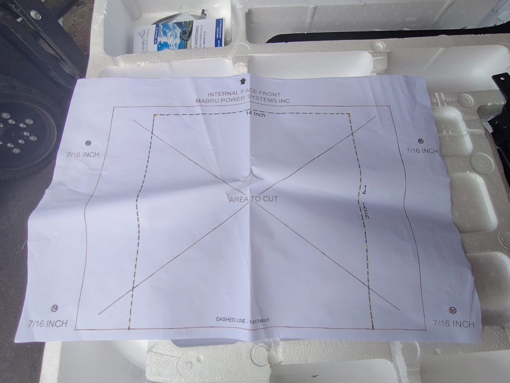
The easiest method uses the native opening size (no modifications), but we’ll guide you through modifying it for a standard 14” x 14” hole.
-
Cut the template and use it to mark your roof opening, ensuring precise measurements.
- To use the paper template, cut out the opening with a razor blade or scissors. In this case, for the 14” opening, we’ll be cutting along the dotted line. Some installers prefer to transfer the template to plywood for a more rigid template.
- Prep pro tips: tape plastic underneath to catch metal shavings and use a large piece of plywood with a blanket underneath to distribute weight on the roof which will prevent indentation. It’s also very helpful to tape the area of the sheet metal that will be cut out to help stabilize it and prevent it from falling through and shearing during the cut. You might even stop periodically during the cut to re-tape areas.
-
Cut the main roof opening AND drill the 4x mounting bolt locations with a ½” drill bit.
- If you’re using a jigsaw with a metal blade, you can expand the pilot hole you might have made earlier when locating the installation area, or you can drill a new pilot hole in one corner, inside the cut-out line that is wide enough for your saw blade and then drill another hole opposite the first. Most installers are using either a jigsaw or metal cut-off disc on an angle grinder.
- File the edges, clean the area, and apply rust-prevention paint to all bare metal.
Installation using a “standard” 14″ x 14″ roof opening
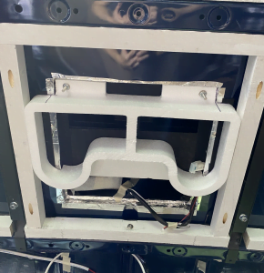
The photo shows the unit turned upside down with the baseplate facing up. The area with the blue painter’s tape indicates how the unit would drop in over a standard, 14” x 14” roof opening. You can see that the area for the cold air outlets (larger, upper rectangular hole) and return air (lower, smaller, 2x, rectangular openings) fits comfortably within this space.
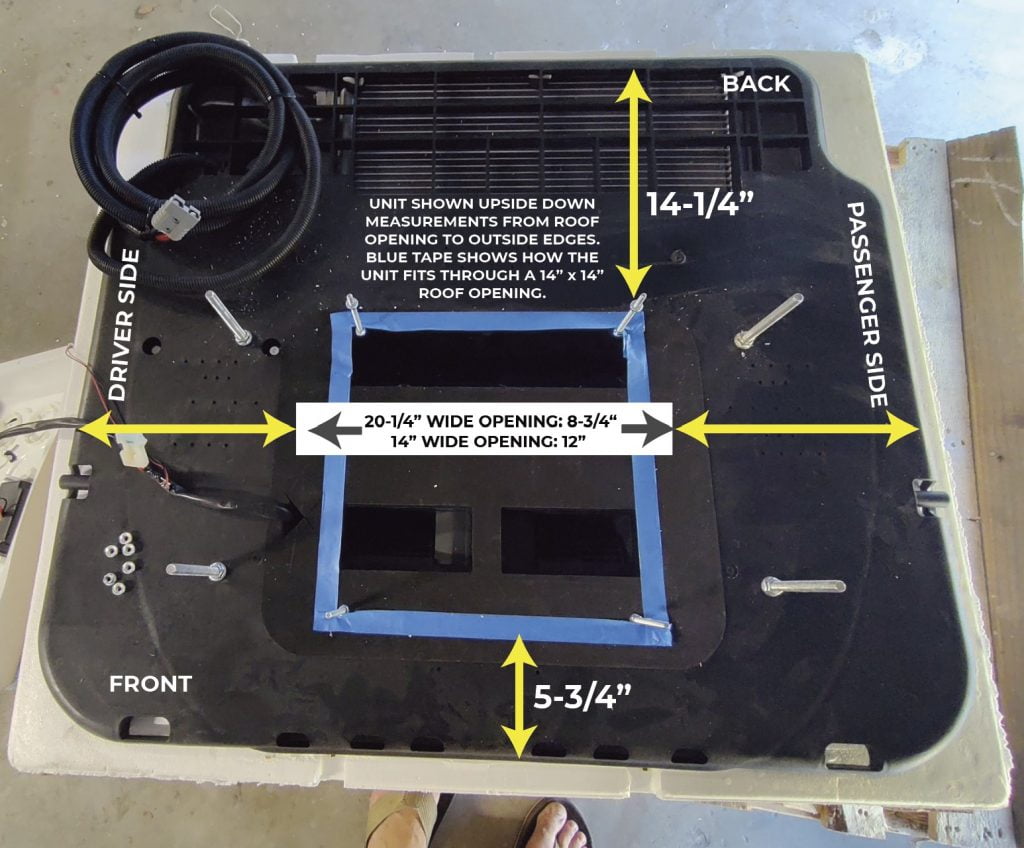
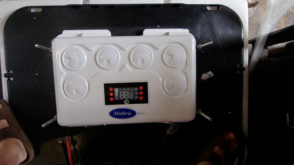
However, the interior panel/vents are wider than 14″ (about 18″ wide) which you can see in the image below. So, if you want to install the unit into a standard opening size, you’ll have to do some basic modifications. Since most of our customers want to use the 14″ x 14″ (standard size) roof opening, this is the process we will detail in the rest of the post.
Step 2: Installing the Gasket and Sealing
-
Place the gasket around your roof opening (and bolt holes), ensuring it forms a rectangle.
- You’ll want to place the rubber gasket around your openings. It ships flattened. Start by stretching the two sides apart from each other to begin reshaping it into a rectangle (video of this process below). One side has an adhesive below a protection tape and the other side does not. We place the side with the adhesive down onto the sheet metal of the van so that it will stay positioned while we seal it.
- The gasket should form a rectangle around the perimeter of your roof openings – both the bolt locations and the 14” opening (see photo below). It can be difficult to get the gasket reshaped and positioned correctly but it is possible with enough care and time. For van models with a prominent roof curve (IE Ford Transit), You may need to cut the gasket so that it fits snugly around the outer bolt holes. See photo below.
- Later in the installation process, the AC unit will be placed on top of this gasket and eventually bolted down such that the gasket will compress to create a waterproof seal. So, it’s important that all the bolt holes are inside the perimeter of the gasket.
- We recommend using a marine sealant such as Loctite PL Marine or 3M 5200 around the inner and outer perimeters of the gasket.
-
Fill in any roof corrugations if needed and apply marine sealant around the inner and outer perimeters of the gasket.
- If your roof has corrugations where the gasket is positioned, you’ll want to fill these in before placing the gasket. There are a number of methods to accomplish this. DIYVans in Oregon sells very nice adapters, you can fill in the valleys with layers of butyl tape or buy/cut PVC adapters like we sell for a Promaster van. If you use butyl tape or PVC adapters be sure to follow up with a generous layer of Dicor lap sealant.
Step 3: Mounting the unit onto the roof
Lift the AC unit onto the roof with help (2-3 people). Typically it’s best to leave the unit in the box while lifting. We use a forklift which works great but not everyone has that luxury. Scaffolding also works well. Two people on ladders is tricky but it gets the job done. Once it’s on the roof, you can carefully unbox it and turn it upside down on the roof such that the exterior shroud/cover is on the van roof and the interior panel/vents are facing up.
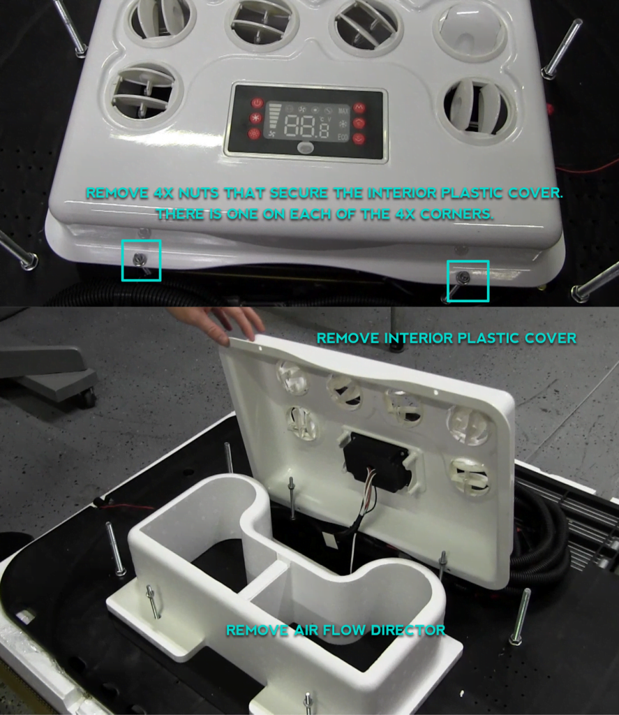
Since we’re installing this into the “smaller”, 14″ roof opening, you’ll need to remove the interior panel/vents and styrofoam air director to be able to place the unit through the opening. Start by removing the 4x, 10mm nuts that attach the interior panel/vents to the unit then you can lift it off. As you do, find where the wiring harness is attached to the baseplate of the AC along with a temperature sensor and carefully cut this wire tie to release the wires. Once the wires are released the interior panel/vent should lift off completely. Next, remove the styrofoam air director that is below. This will need to be modified later, so you can set it aside for later in the installation.
With everything ready, you can now place the AC unit over the gasket/opening and bolt it down using the metal mounting brackets. We recommend that you recruit a few extra people to help you with this step. It works best with two people on the roof positioning the AC unit into the right place with another person inside the van holding the interior panel/vents that need to be passed through the opening and managed safely while the rest of the unit is positioned, otherwise, it will sort of dangle and can be damaged. The inside person can also guide the folks on the roof on positioning since the most difficult part of the process is getting the bolt holes lined up correctly so the unit can drop into place. If necessary, you can expand the ½” bolt holes with a step bit to make the 4x bolts line up for dropping into place. Be cautious not to over-tighten, and consider attaching the brackets to the roof supports.
Step 4: routing the wiring harness
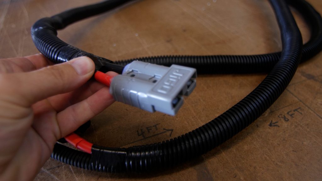
There is an approximately 11-foot piece of wiring harness that comes off the unit itself that is terminated with a grey, Anderson connector (photo below) and there is another section of the wiring harness that is also approximately 11 feet included in the kit that has a pairing Anderson connection to extend the wire from the unit to your 12 volt DC bus bar. The wiring harness is two 6 AWG wires, one red for the positive DC supply and the other black for the negative. The positive wire includes an inline, 80 amp fuse to protect the circuit. Since the Mabru uses around 55 amps on max, it’s too high a draw to wire to a typical DC fuse panel/load center. So, many installers will connect the wires to the “right side” of a Lynx Distributor that is designed to attach to another Lynx Distributor to expand the connections available. You don’t need to use a fused terminal on the distributor because of the fuse provided on the wiring harness.
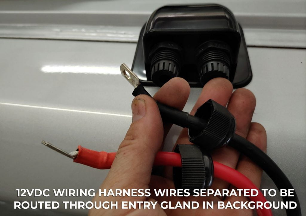
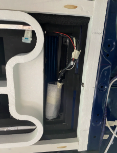
Begin the wiring harness routing by deciding on the location for your solar entry gland that will provide a waterproof path for the wiring harness through the roof to wherever your electrical system is located. We recommend locating the entry gland behind the unit as closely as possible while avoiding any structural supports or other obstacles inside the van. After you drill the hole for the wires, that the entry gland will “cover” we recommend using a rubber grommet to protect the wires from the sheet metal, and don’t forget to file and paint this exposed metal as well. Also be sure to fasten the gland to the roof and seal it with a lap sealant like Dicor. You’ll also want to make sure the wires are protected by wire loom and any length of wire secured to the roof. Self-adhesive cable tie mounts work well for this purpose.
Next, you’ll have to choose how you want to get the wiring harness through the hole you created. The tricky part of this routing is that the Anderson connection at the end of the section of the wiring harness (photo below) prevents you from being able to route the black and red wires through the “glands” on the solar entry since they cannot be separated. There are a few ways to manage this.\
- Option one is to remove the wires from the Anderson connection temporarily to get them through the entry gland and then put them back. You can do this by opening up the connector with small screw driver.
- Option two is to cut off the Anderson connector about 6” from the end with the connector of the wiring harness section that comes off the Mabru unit, separate the wires to get through the entry gland, and then splice it back on using 6 AWG butt connectors and heat shrink.
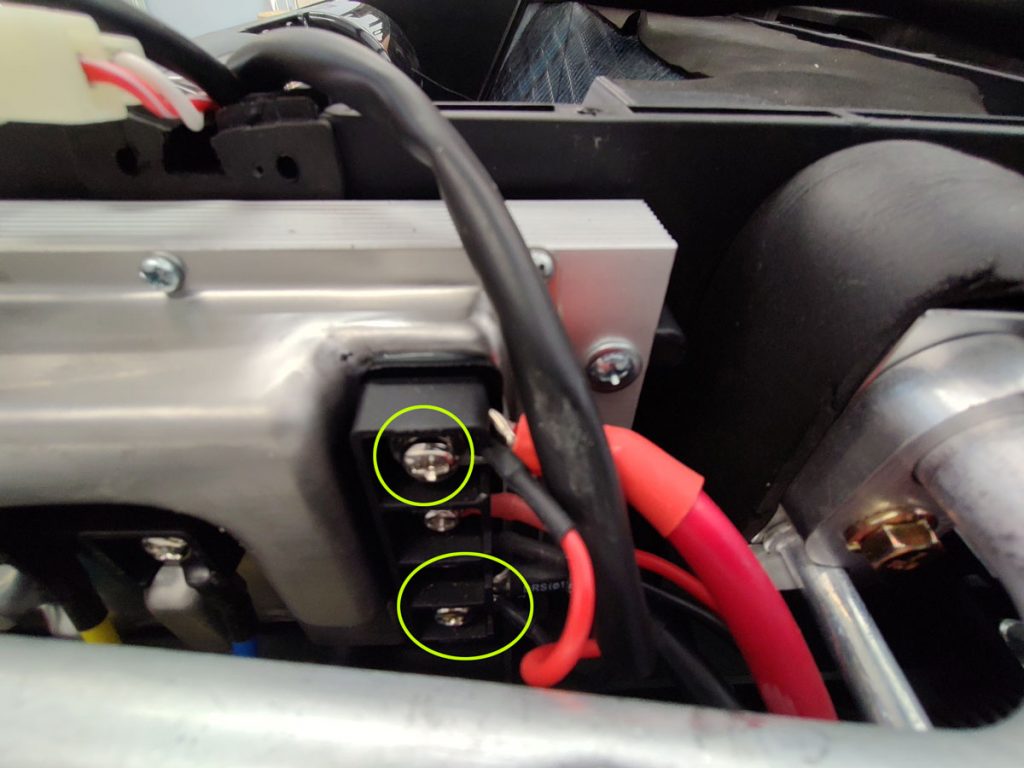
- Option three is to remove the exterior shroud/cover from the Mabru unit to locate where the DC supply wires connect to the unit itself on the left side (driver side) and disconnect these wires. This allows you to separate a section of the red and black wires to route through the entry gland and then you can reconnect the wires to the terminals on the AC. Below is a photo of these connections.
With the AC unit mounted on the roof and the wires routed to the interior, we can move on to the interior installation! Woot!
Step 5: Interior Installation
Assemble the supplied mounting brackets and secure the AC unit to the vehicle. The brackets come in 6x pieces that will be assembled into 2x separate bracket assemblies – one for the passenger side and the other for the driver side. The bracket pieces are painted black but they often get a little dinged up in transport. However, they are stainless steel and, in most cases will be hidden away in your ceiling, so there is no need to be concerned about any small dings. You’ll take one “middle” section and pair it with two “extensions” (photo below). The “middles” do not have “flanges” on the end and the “extensions” do.
Place a middle flat on a surface with the C-channel facing down and the bolt holes facing up then grab an extension and turn it so that this channel is facing up and the flange is on the flat surface. Then slide the extension into one end of the middle. Do the same on the other side of the middle. Now you have a bracket that can expand from both the front and rear to the length needed to span between the structural supports that form the front and rear of the “bay” you installed the AC into on the van roof. The maximum span is about 30” from front to back when the extensions are fully extended.
Below is a video of this process. Worth at least a few thousand words.
Once you’ve assembled both brackets, using all 6x pieces, you can install them onto the passenger and driver side, over the mounting bolts from the AC unit that are now hanging down into your van. The holes in the brackets should line up with the bolts and you want the flanges on the end of each extension to press firmly against the van supports. If there isn’t a factory support structure where your bracket flanges land, you will have to install your own support with adequately sized metal or wood that is attached to the vehicle roof with something like a heavy-duty construction adhesive.
The brackets are held in place with the supplied, 15mm nuts. You’ll want to tighten each of the 4x nuts in a rotating fashion – moving from one nut to the next in circulation so that you can create even pressure around the gasket. You want to make sure that the gasket (on the roof between the AC unit and the roof of the vehicle) shows some compression. Don’t exceed more than 15 newton meters of torque. Once torqued down you can choose to use the provided, black screws to attach the “flange” part of the brackets to the roof supports if you’d like. We don’t typically do this since the system is so tightly installed.
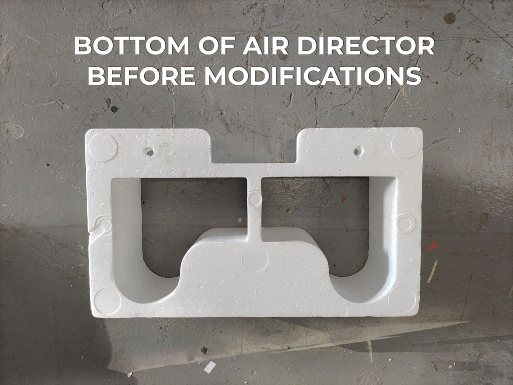
Reshaping the styrofoam air director to fit your desired ceiling height and fit the 14”x14” hole
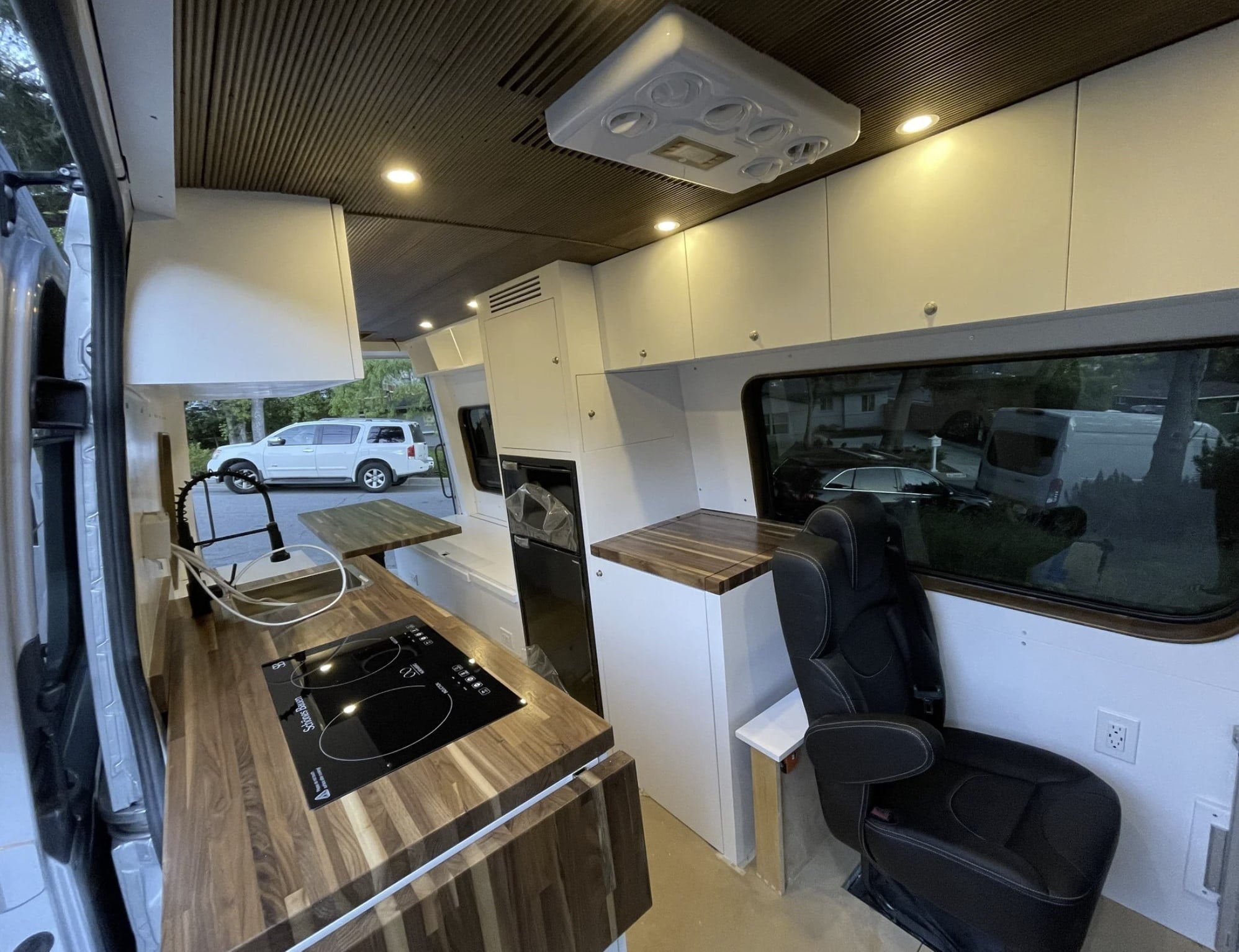
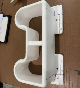
Pause for a minute to take a look at the interior of the AC at this stage. On the baseplate, there is a thin layer of foam. In the front part, there are two rectangular openings. This is where the cooled air comes out. To the rear of that is one larger rectangular opening. That is where air is pulled into the unit from the interior of the van to be cooled. See the image below.
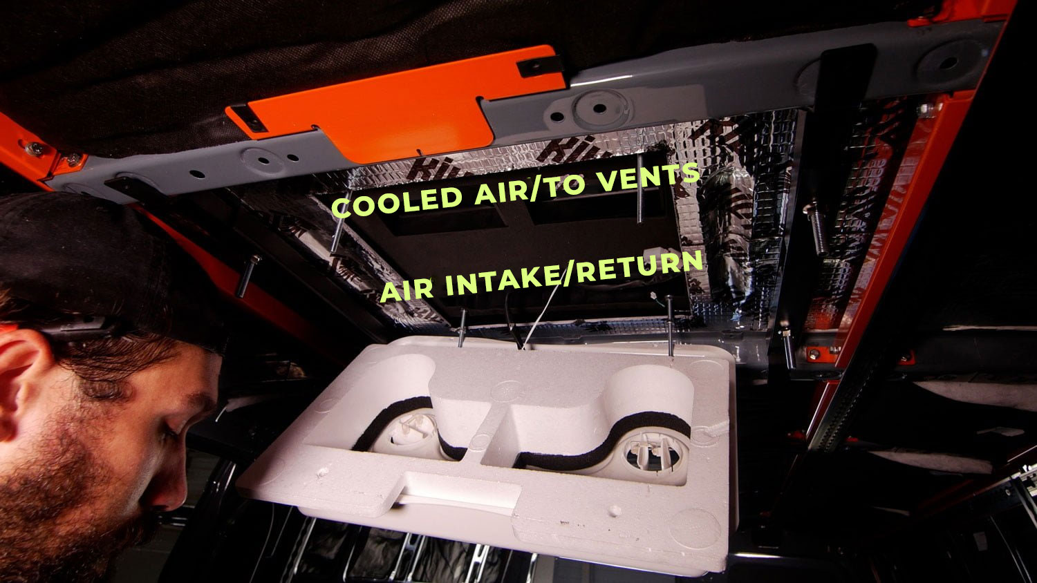
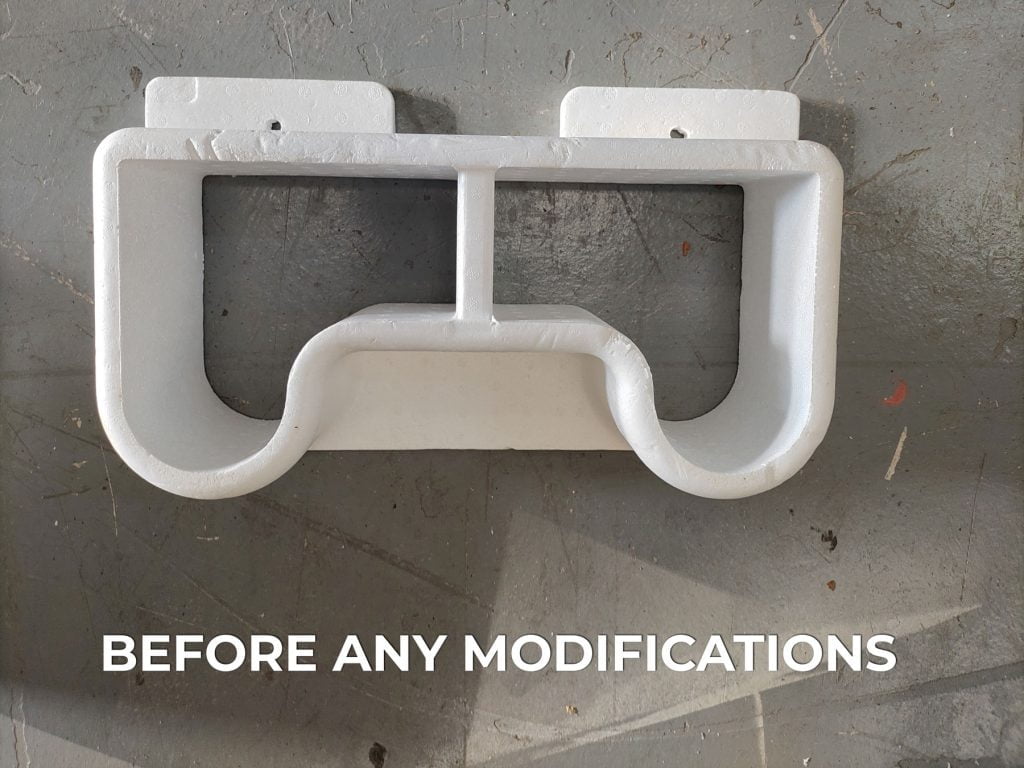
The function of the styrofoam air director is to, you guessed it, direct the cooled air to the vents. You can see that the shape of the foam is the same as the vents on the interior panel.
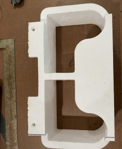
If you were installing into the Mabru’s native (larger) roof opening size, the styrofoam air director does not need to be modified since the opening would be large enough for it to press against the baseplate with no modifications.
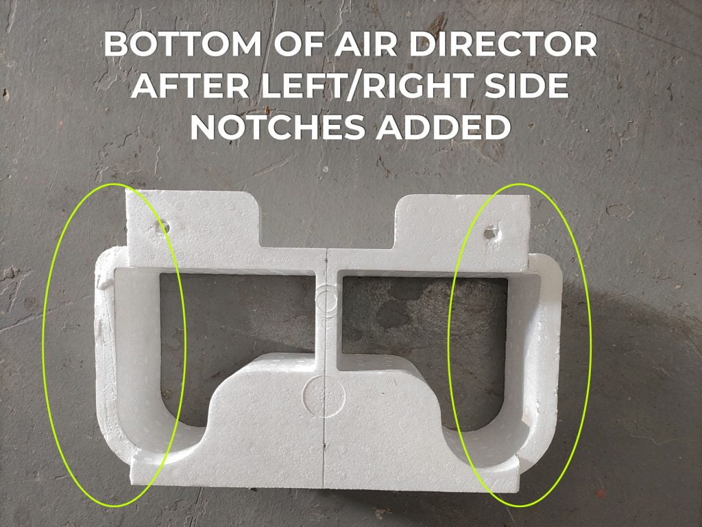
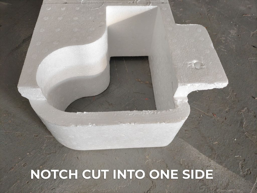
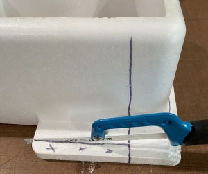
But, if you look at the 14” opening install, the air director is wider than the roof opening and where it passes the area where the Mabru base plate is visible you can see that the metal roof of the van is “lower “. Since it’s no longer one flat plane, we have to essentially reshape the air director so there is a notch on the driver and passenger sides. We’ve tried a number of tools for this and a serrated knife or a hack saw blade, removed from the saw, seems to work the best. You can hold up the air director inside the van in the area where it is installed – lined up with the bolt locations with the air vents facing forward and mark where the notches need to be cut.
Below are some images of this process. Click on any image to open it larger.
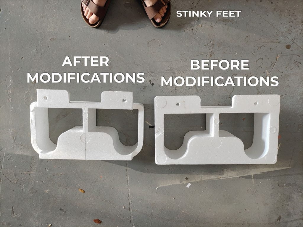
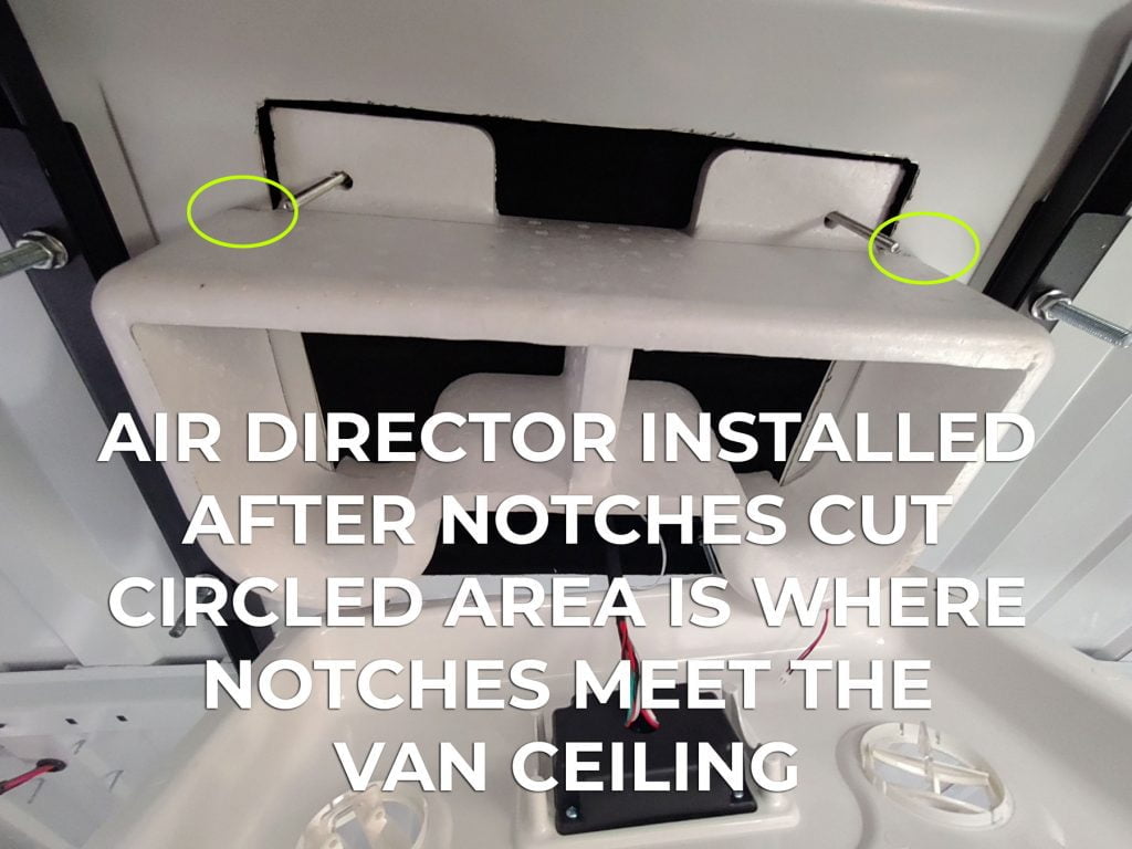
Once you have the notch cut, you can consider another modification: Depending on how deep your interior ceiling will be – which is normally a combination of the van’s metal supports, furring strips, and ceiling material if you want the interior panel/vents to be as high as possible so that it doesn’t come down into the living space as much, you can shorten the foam air director to the height that you need. This is optional.
One additional tip on all this surgery: if your modifications are a little sloppy you can use foam tape lon the cut portions so that, when the air director is installed into place and the interior panel/vents are installed, it will be pressed up against the baseplate/van metal and the foam will compress to fill any small gaps. This is important because you want as good of a seal between the air director and the baseplate on the AC so that cooled air doesn’t leak into the ceiling cavity or anywhere else it’s not cooling your rig.
Putting it all back together
With the foam director reshaped, you can now reassemble it with the interior panel/vents.
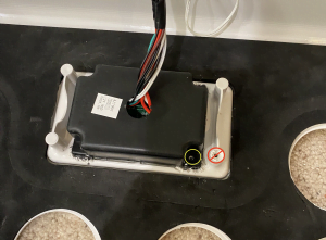
You want to re-attach the wiring harness and temp sensor to where it was wire-tied before. The temp sensor needs to be in that location, directly adjacent to the air return to sense the temperature of the air inside the van. This is how the thermostat on the unit works.
Now you can re-install the interior panel/vents by sliding it over the 4x bolt locations and re-attaching the 10mm nuts to secure it into place. Note that there are two sets of bolts for the interior panel/vents, you can raise or lower the lower bolt to set the correct height of the interior unit if you’ve cut down the styrofoam air director.
Return air: ensure proper venting for return air to avoid cycling issues
When the unit is running you can use the various vents to direct the cooled air. One thing to keep in mind is that you don’t want to create a situation where the cooled air is going “directly” into the return air vent(s) such as pointing the cool air vents directly at the return area. If you do that, the thermostat will interpret this cool air coming from the AC unit as the “interior air temperature” causing the AC unit to cycle the compressor on and off too rapidly. Instead, you want the return air to be more representative of the actual ambient air temp inside the living space.
Some customers prefer to make their own return air grille. The return air trim ring that comes with the Mabru is unnecessarily large and unattractive.
Directly below are some photos of what some of our customers have done.
Note, the return air grille should be at least as big as the return air opening on the baseplate of the unit itself, if not a little larger.
Finish wiring
At this point you’re ready to finish routing the wiring harness to your 12-volt DC supply – often the right side of a Lynx Distributor or other bus bar connection.
Powering on, testing, and tips
Now you can turn it on for the first time and ensure that it’s working! In our testing, with a laser thermometer, we normally see between 25-30 degrees F delta between the temperature of the air coming into the unit and the cooled air coming out after a few minutes of operation on “max” mode. When it’s really hot inside, this might look like 90 degrees inside the van and 65 or 70 degrees of cooled air coming out of the unit. Over time, as the interior temperature goes down from the cooling effect of operating the AC, the cooled air will get increasingly cooler.
On very hot days, we recommend pre-cooling your van as you drive by running your vehicle air conditioner as powerfully as you can AND running the Mabru unit on high. The initial cooldown of the living space takes much more cooling/energy than maintaining the temperature. In many camper vans or RVs the house battery bank, that is powering the Mabru unit will be charging from the vehicle alternator while driving and some of that energy can power the AC unit without discharging the battery as much. Then, when you arrive at your destination a pre-cooled van can generally be kept cool by the Mabru even in low or eco mode.
Obviously, the size of the van, how it’s insulated, the exterior color of the van, using insulated window coverings, and locating the van in the shade all help a lot as well.
The remote control is pretty confusing so we have a handy “guide” that maps the buttons to the various functions.
Congratulations, you’ve successfully installed the Mabru 12000 BTU rooftop air conditioner in your van! Now you can enjoy cool, comfortable journeys during even the hottest days. If you found this guide helpful, please consider supporting our store for other great road-tested products designed to support DIY van builders like you. Stay cool out there, and happy van adventures!
As of 2026, we no longer have any stock of our flush mount interior faceplate.
Bonus Instructions for customers who purchased a Flush Mount Faceplate for Mabru RV12000 Air Conditioner
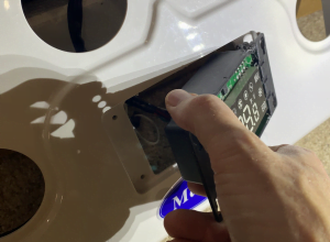
There are a few easy steps to relocate the electronic Control Panel from the factory trim piece to your new Face Plate.
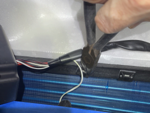
Step 1. Using a wire side cutter, carefully snip the zip ties holding the wiring harness and the temperature sensor from the inside of the return air cavity. This will allow you to move the factory trim piece off to the side for convenience for the next steps.
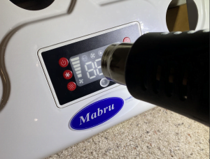
Step 2. Remove the four screws on the black control panel housing on the back side. No need to pry up here as I did the first time… there are four more screws on the front side.
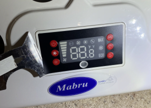
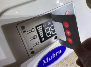
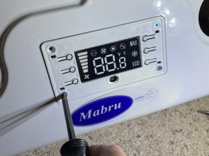
Step 3. Remove the Control Panel face sticker to reveal four screws behind it. You can add a little heat from a hair dryer or heat gun to soften the glue a little. Carefully remove the sticker using a putty knife or similar wide blade. The sticker is pretty durable, but you don’t want to nick it as you will re-apply it once the control panel is installed in the new flush mount face plate.
Step 4. Remove the four phillips head screws and the white trim piece. Pull the control panel forward and rotate 90 degrees, then pull it back through the factory trim piece.
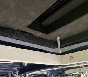
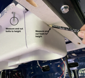
Step 5. After the A/C unit is mounted on the roof as described in the other sections, cut off the 4 bolts so they are above your planned ceiling height. The front two bolts should be left long enough to secure the styrofoam deflector.
Step 6. Cut the styrofoam deflector so that it fits flat against the black bottom of the A/C unit (trim away the excess that hits the metal roof of the van. The table saw with a tall fence works great.
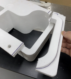
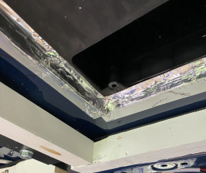
Step 7. To ensure the air will not short circuit, you can install 1” thick foam tape between the roof of the van and the A/C unit and cover it with aluminum tape.
Step 8. Hold the foam piece in place and mark the location of the ceiling framing. Then add the thickness of your ceiling material and cut the styrofoam to the correct height. Then install the foam, securing it with the two front bolts. You can also use thin foam tape to close any gaps to prevent the air from short circuiting.
Step 9. If you use very thin ceiling boards, such as ¼” cedar, consider installing 2×2 framing on the sides of the Styrofoam such that the screw holes in the Face Plate align with the framing. Otherwise, you can screw directly into the ceiling material to secure the Face Plate.
Step 10. Re-install the control panel removed in steps 3 & 4 in the same way, insert it through the hole in the flush mount faceplate then rotate so the screw holes line up. Install the white trim piece and four Phillips screws, then the face sticker can be re-applied.
Step 11. Replace the four screws on the black control panel housing on the backside.
Step 12. Use two new zip ties to re-attach the wiring harness and temperature probe from step 1 above.
Step 13. Secure the flush mount faceplate to the ceiling using screws of your choice. Thin foam stripping can also be applied on the bottom of the styrofoam deflector to provide an air-tight fit with the faceplate. (You may need to glue wood or metal strips on the backside of the panel to help the screws grip into the control panel).
As always, if you have any issues or questions with installation please give us a call or email us.