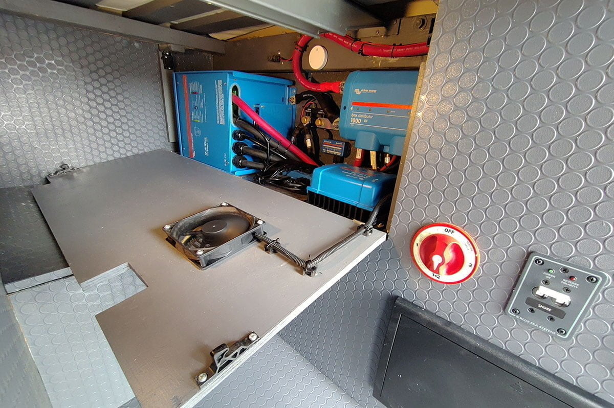
We often get asked about ventilation and fans to keep an electrical system cool under loads. After all these power system components can get pretty warm when running AND they’re very often tucked away under a bed or inside a cabinet.
Also, if Victron Energy equipment gets too hot, they start “derating” which basically means that the ability of the device to perform at it’s highest performance is decreased in relation to the temperature. For instance, if you have a MultiPlus 12/3000/120 inverter/charger that is rated for about 2,400 watts at 77 degrees Fahrenheit, and if the temp goes up to 104 degrees, the output is “derated” to 2,200 watts. Below is a table taken from the spec sheet for the unit that illustrates this pretty clearly. Or, if you really want to nerd out, Victron has this white paper. Similar “derating” happens on other devices such as MPPT solar controllers or DC-DC chargers, etc.

So, what to do for ventilation? The simple answer is to add as much “passive” ventilation as you can and try to have at least two vent locations to allow the air to flow through the area. There are lots of ways to add vents to cabinets that I don’t think we need to cover here! Anyway, there is an online store called Amazon.com (I know, weird name), that sells a variety of things including these circular vents that we’ve used often.
But, practically speaking, sometimes, passive cooling just isn’t going to do the trick so we wanted to share how to add some “active cooling” with computer fans that only turn on when the temperature in your electrical system area reaches a particular temperature. To do this we’ll use a Ruuvitag (wireless, Bluetooth temp/humidity/air pressure sensor) and the built-in relay inside a Victron Energy Cerbo GX.

Connecting a Ruuvitag To A Victron Cerbo GX
Ruuvitags are small, affordable sensors that are incredibly easy to deploy since they can communicate wirelessly with a Victron Cerbo GX. They come in three versions. We’ll be discussing the baseline, 4-in-one Ruuvitag (temperature, humidity, air pressure, and motion). There is also a water-resistant 3-in-one version (temperature, humidity, and motion) as well as a fully waterproof (submersible) 2-in-one version (temperature and motion only).
In our vans, we like to put these Ruuvitags in various places – one in the main living space, another near the power system, one outside, and sometimes one in the fridge too!
Victron Energy recommends using a USB to Bluetooth “dongle” to increase the Bluetooth signal reach on the Cerbo GX. These are quite inexpensive (around $10) and make a big difference. We have a few recommended/tested options on the product page (in the description).
To add a Ruuvitag to your system, start by pulling the plastic strip out from the side. This will turn the Ruuvitag on by allowing the battery to connect to the circuit board.
Next, on the Cerbo GX, navigate to “menu -> settings -> Bluetooth” and ensure that it’s “enabled”. Then go to “menu -> settings -> I/O -> Bluetooth sensors” and make sure that they are enabled as well. Once these two settings are enabled, you should see the Ruuvitag appear on the I/O screen or on the first menu screen. You can navigate to the main menu screen by going back to “pages” and then pressing “menu” again or simply pressing the “back” button a few times to get to the main menu.
On this main menu, you should see the Ruuvitag appear as something along the lines of “generic temperature sensor”. If you press on this device in the menu, you’ll open the Ruuvitag’s menu. You can check that you’re interacting with the right device by confirming that the “product” is a “Ruuvitag”. Next, you can give the Ruuvitag an appropriate name by navigating to the “device” option and then pressing on “name” which will launch a keyboard so you can name it something such as “Power System”.
Now, if you haven’t already, you might want to switch the temperature units from Celsius to Fahrenheit (menu -> settings -> display & language -> units). If you don’t see this option, you’ll probably need to upgrade your firmware on the Cerbo GX to the latest version of Venus OS (menu -> settings -> firmware -> online updates). The same goes for if the Ruuvitags are not being “seen” by your Cerbo GX – updating the firmware will likely fix that as well.
It’s worth mentioning that having temperature data on the Cerbo GX is pretty darn useful in other scenarios as well. For instance, if you have your system configured to send data to Victron’s free cloud service called VRM, you can get notifications pushed to you via email. Imagine if you’re traveling with a pet and you want to be notified if the interior temp goes above 85 degrees.
Adding A Temperature Triggered Fan With a Cerbo GX
Now that we have a temperature sensor with the Ruuvitag, we’ll dive into wiring up a fan (or multiple fans) to one of the relays on the Victron Energy Cerbo GX.
You can use pretty much any 12-volt DC-powered fan and even combine multiple fans/loads running off the relay. In my van, I choose these fans and paired them up with these vents. The one limitation to be aware of is that the relay is only rated for 6 amps at up to 30 volts DC. However, most computer fans use very little power.
There are two built-in relays on the Cerbo GX. Relay #1 has a lot more options as you can see in the screenshot below comparing the “function” choices for relay 1 and relay 2. For this reason, we recommend that you use relay 2 for this kind of “temperature” trigger so that relay 1 can remain available for other functions such as a generator start/stop, etc.

Start by opening up the relay 2 options on the Cerbo GX (menu -> settings -> relay -> function (relay 2)). Then choose “temperature” from this menu as illustrated on the right side of the image above.
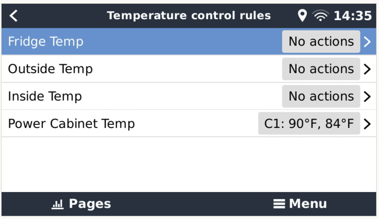
Now, if you go back one menu with the “back” button (arrow in the very top left portion of the screen), you’ll see a new menu called “temperature control rules”. Below is a screenshot of this menu showing the various Ruuvitags in my van (temperature sensors) connected to the Cerbo GX.

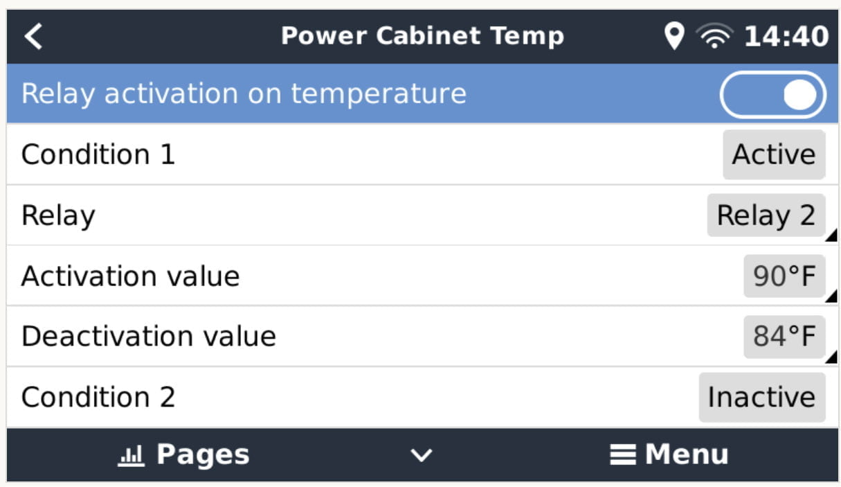
The next step is to choose which temperature sensor/Ruuvitag should be used as the relay triggering sensor. In my case, that’s the “Power Cabinet Temp”. Press on that sensor to open its menu which looks like the following.

This is where you’ll configure the specific conditions where you want the fan(s) to turn on and off which are the “activation value” and the “deactivation value” respectively. Notice that there is a way to set two “conditions”. In our example, we’ll only use one. I have my fan set to come on at 90 degrees and to turn off at 84 degrees.
If the “activation value” for “condition 1” has been met (temp inside the power cabinet is above 90 degrees), as was the case when this screenshot was taken, the “condition 1” will show as “active”. If not, it will show as “inactive”.
Configure your activation and deactivation values to your liking – you can always return to this menu and change the settings!
Wiring The Relay
The last step is actually wiring up the relay. The Cerbo GX comes with a bunch of black terminal blocks that can plug into the bottom of the device for tank monitoring, relays, etc. So, you’ll need one of those.
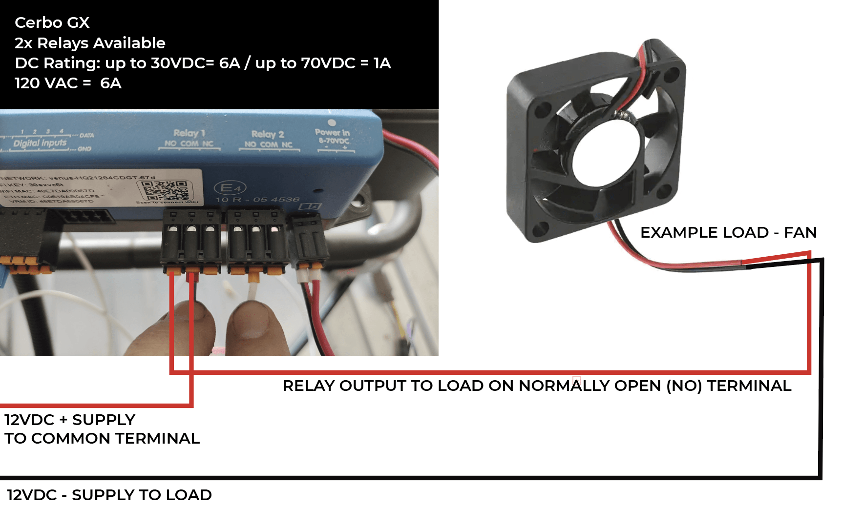
The illustration below outlines the wiring of the relay. The post discusses using relay 2 instead but the wiring illustration shows relay 1. The great thing about the terminal blocks is that they can be remove for ease of wiring and also be swapped from one relay port to the other.
I think the illustration describes the wiring better than I can do in words, but basically, you’ll supply 12 volt DC positive from your system – likely from your 12 volt load center/fuse box, which will connect up to the relay’s “common” connection. The 12 volt DC negative wire can go directly to the fan/load since only the positive side of the circuit will be controlled by the relay. Then you’ll wire the NO (normally open) connection to the fan/load’s DC positive terminals.

And that’s it! Now you can test the relay by adjusting the “activation” values to be close to the ambient temperatures and/or carefully heat up the Ruuvitag with a heat gun until the activation value temperature is met and you should see the relay come on (contacts close) to power your fan(s)/load!

