We worked extensively with Victron Energy and Wakespeed to design a system that will work reliably and safely! However, electrical systems are complicated and we recommend that you either have your system installed by a professional or, if you do it yourself, have it inspected by a professional when it’s completed. Please use the information provided at your own risk.
Follow this link to gain access to our library of FREE Camper Van Electrical System Wiring Diagrams. Use the PDF files to print/zoom in.
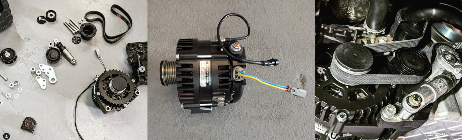
In this blog post, we dive into a massive, 48-volt secondary alternator power system for mobile applications like a camper van or RV using the Nations 48-volt alternator kit, paired with a Wakespeed WS500 regulator and a bunch of Victron Energy components. You can buy all the components necessary in one best price bundle in our store.
Update February 2024. We wrapped up the installation before our Peace Love & Vans event in early February 2024 (the one with the epic weather!). The system performed even better than our expectations producing over 5,000 watts of power and sometimes over 6,000 watts at typical “driving RPMS. Also, as expected, it doesn’t do anything at idle. So, this is a system that is amazing for anyone doing some driving – even if it’s just short distances between your campsite and sightseeing/grocery shopping! If you’re planning on using at idle, you should consider the “high idle kits” we discuss in the post! Jump down the results video and installation photos.
Update January 2025. Victron has released their NG (new generation) Smart Lithium Batteries including a native 48-volt battery (51.2 nominal voltage). As a result, we’ve slightly redesigned this system to use those batteries instead of using 2x 24-volt batteries in series. The NG batteries have a bunch of new features you can learn about in this video. Please us the diagram link above or for the updated system example wiring diagram. If you’re looking for the older examples you can use the following for the 2-battery and the 4-battery example diagrams.
We put a lot of time into developing, testing, and documenting these systems. The resources are all free but we can only afford to do this because folks support our store!
A few years ago we introduced our 12-volt secondary alternator power system, along with all the same kind of resources that made installing an advanced power system like that accessible to tons of our customers.
Why a Secondary Alternator?
Instead of huge battery banks, we like to focus on huge charging sources and “balancing” our battery bank size with the ability to get it recharged on a regular basis. We see a lot of customers with massive battery banks (think 1,000 amp hours or more) but try to rely on relatively tiny charging sources such as solar and DC-DC chargers. DC-DC charging is generally limited to about 50% of your vehicle’s factory alternator and solar is primarily limited by the small available space on a van roof – particularly when you have other things up there like Maxxfans or air conditioners.
It just makes sense that, as you increase your battery storage capacity, you need to increase your charging capabilities. That’s where the secondary alternator comes in. These secondary alternators are designed specifically for high current charging, including external regulation from a device like the Wakespeed WS500 Pro for advanced charging in a way that keeps your batteries happy. That last point is pretty important since your batteries are one of the most expensive parts of your electrical system! The combo of the alternator and regulator is much like having a pretty big generator that is powered by your engine when you drive. It does put a load on the engine but it’s similar to other belt-driven stuff like your van’s air conditioner.
Va Va Voltage – 12 vs. 24 vs. 48
Big picture, I think that most people should just stick with 12-volts unless they really need the benefits of a higher voltage system. 12-volts is very reliable and simple considering most “loads” running off a system are 12-volt or powered by an inverter supplying 120 volt AC.
Our thoughts on 24 Volt systems have changed over time. You can read about why a 24 Volt system with secondary alternator or 24 Volt system (without secondary alternator) may be right for you. For those looking for massive alternator-based charging power, we still believe that a 48 Volt system is the best option.
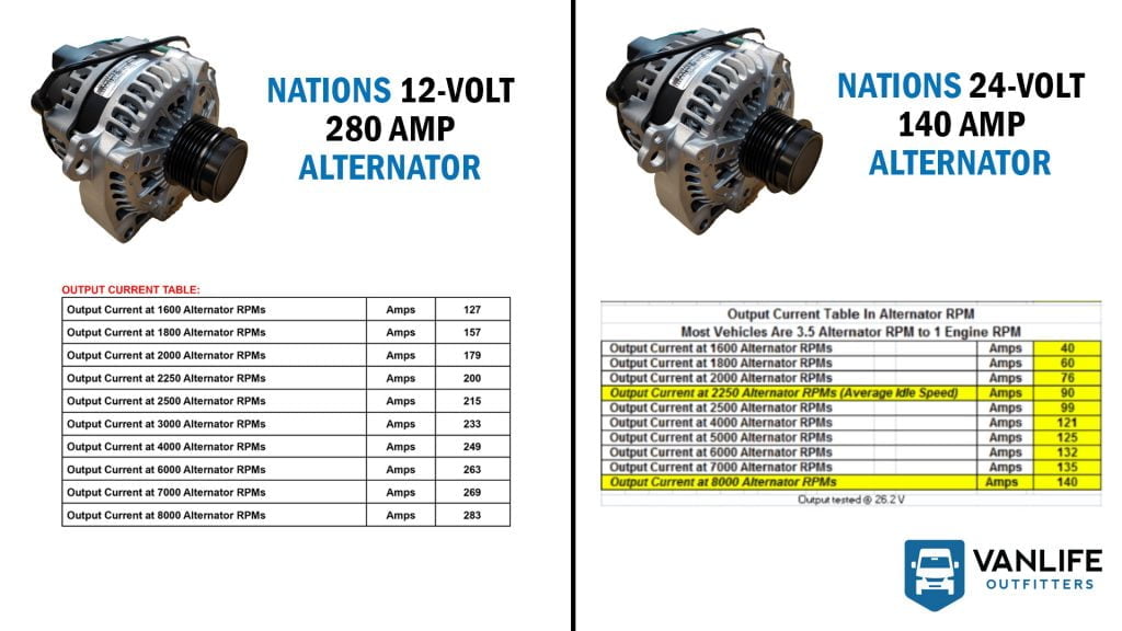
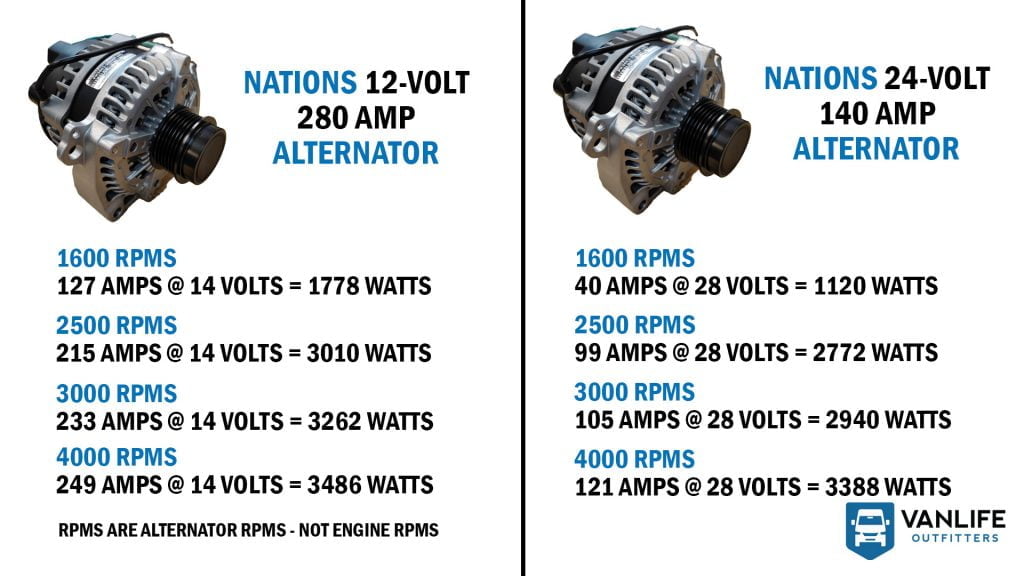
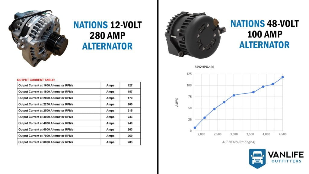
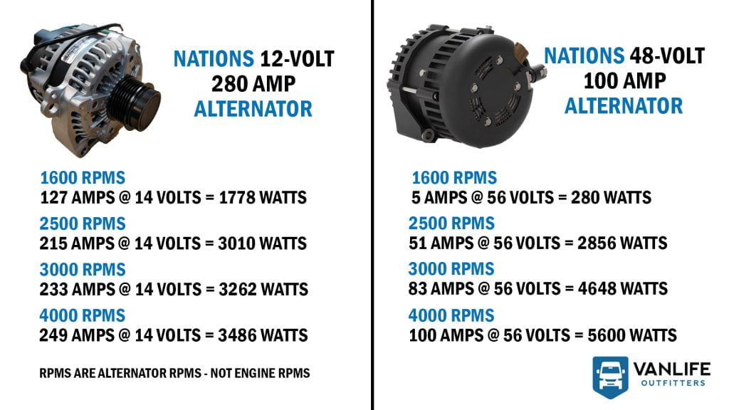
Take a look at the graphics below that compare Nations 12-volt, 280 amp alternator with the 24-volt, 140 amp alternator and the 48-volt, 100 amp alternator.
The 48-volt alternator output is considerably higher which is one of the main reasons to consider a higher voltage system. At higher RPMs, it can produce about 70% more watts than the 12-volt alternator as you can see in the graphics below. So, if you need it, the jump from something like 3000 watts to something like 5000 watts of charging may be compelling enough to pay more for and deal with the extra complexity and other caveats (detailed below). In addition, the other advantages of a 24-volt system, like smaller wires, higher efficiency, and less heat are doubled with a 48-volt system.
Native 48-Volt Loads – Air Conditioner
Another advantage of a 48-volt system is the ability to run loads that are native to 48-volts like the impressive Nomadic Cooling X3 unit that we’ll be putting into our 48-volt test vehicle. Stay tuned for more blogs and videos about that! It’s the most powerful DC unit on the market and also very quiet and energy efficient – particularly compared to older, 120-volt AC rooftop options.
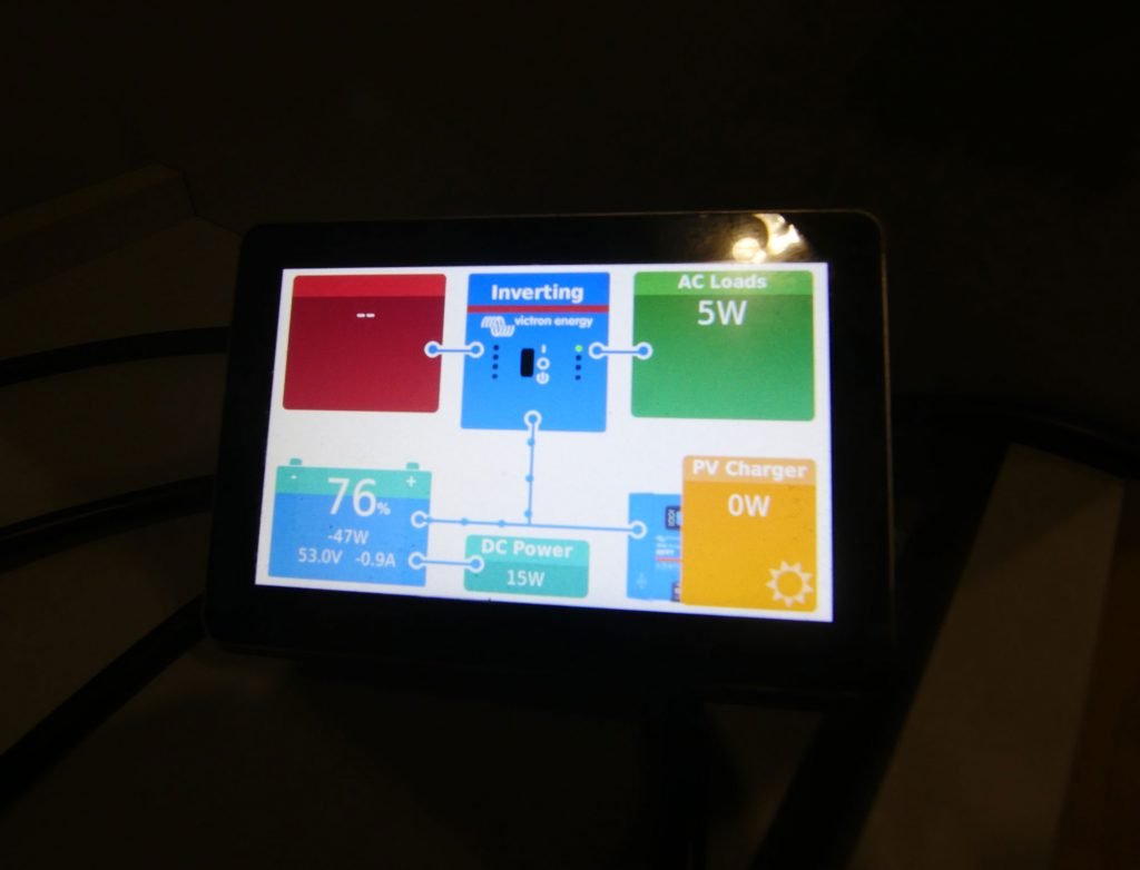
The Benefit: Super Fast Recharging
As an example, let’s say you’re camping off-grid down here in Florida in the summer so you run your 48-volt air conditioner all night long and maybe have a fan running plus your refrigerator and other smaller loads. You might wake up in the morning, take a look at your Touch 50 screen connected to your Cerbo device, and see that the battery state of charge (SOC) of your batteries might be 60% or maybe even 50% meaning you’ve used something like 80 or 100 amp hours of stored power from your battery bank. Keep in mind that in this in this hypothetical story, you using one of the highest draw appliances – air conditioning – in a sort of worst-case scenario of Florida in the summertime. In other scenarios, you might use far less. With this 48-volt secondary alternator system, charging at around 100 amps, you would only need to drive for about 45 minutes to completely restore the power you used! Take a little drive to get some groceries. Maybe a little less if it was a sunny day and your solar panels were pitching in. Incidentally, if you use one of our Isotemp water heaters, connected to your van’s coolant lines, you’d also produce hot water for the next day or so with no additional power use. You see, we like the make use of the vehicle we’re driving around anyway!
Let’s contrast that to using “just” the solar panels. In pretty much perfect conditions, the 4x, 200-watt solar panels shown in our example wiring diagram for this system might produce something like 12-14 amps so you’re looking at over 6 hours of sitting in the sun to accomplish the same thing as the grocery run and there are plenty of times you either don’t have sun or don’t want to park in it! Also, it can be quite difficult to fit so many panels on a roof of a van if you also want Maxxfans, air conditioning, etc.
Surprising Cost Comparison
At the time we’re publishing this blog post (prices change, y’all), the best price product bundle for our example 48-volt power system with 200 amp hours of battery storage at a nominal 51.2 volts (10,240 watt hours) configured with the 150/35 charge controller is “only” about $1,500 more expensive than the equivalent (same battery storage) 12-volt secondary alternator system.
Caveats and Safety
Currently, 48-volt alternators – of all makes/brands – have lower charging output at idle compared to their 12/24-volt counterparts. I’m sure this is being worked on and hopefully, it will improve over time but, for now, this isn’t ideal.
48-volts is high voltage and, as such, requires a lot more skill and care to be installed correctly for a safe system. If you’re going to install a 48-volt system you really need to know what you’re doing because the consequences of mistakes are much higher than a 12-volt system. In particular, “load dumps” can be catastrophic in a 48-volt system. A load dump is when the alternator is charging and there is a sudden, unplanned disconnect between the charging output and the batteries absorbing the current such as a short circuit, blown fuse, or a disconnect switch being turned off thus causing a voltage spike. High-quality 12/24-volt charging alternators, like the ones from Nations, have “avalanche diodes” that are designed to suppress the voltage spikes to something like 32 volts which, while high, isn’t likely to destroy your system components. However, 48-volt alternators don’t have this feature which means that a load dump can result in a 400+ volt spike which is extremely dangerous and will certainly destroy your system. Super duper bad.
It’s much harder to find components that are rated for 48-volt systems – so many of the things that are normally used in 12-volt systems have a max rating of 32-volts or even 48-volts. In our 48-volt system, we’re going to see the battery bank voltage somewhere between 51 and 57-volts depending on the state of charge. We’ve made this easier for our customers. In our example system (see wiring diagram at the top of this page), all the components are rated for 58-volts or higher. Also, we have an entire section of our store that is now dedicated to this higher voltage world of 48!
A 48-volt power system allows you to really scale up your solar system if you have the space for it (let’s say on a skoolie build with a large roof) since the current produced at the same wattage is much lower. But, you also need to be sure that your solar panel array(s) are running at high enough voltage to charge the batteries. Victron Energy solar charge controllers require that the input voltage from your panels (PV input voltage) is at least 5 volts higher than the battery bank voltage. Most solar panels we see our customers output something around 20 volts in optimal conditions and less in suboptimal conditions (cloudy, dusk, dirty panels, etc.). Therefore in a 12-volt system, it’s pretty easy to have the PV input voltage above the battery voltage. In a 48-volt system, you’ll need to be sure to wire enough panels in series (or series, parallel) to get the input voltage up to at least 5 volts greater than the battery voltage. Aiming for the higher end of the solar controller rating is a good idea so that you get some charging from solar, even in suboptimal conditions. In our example system, we show 2x sets of 2x panels in series that are then wired in parallel for something around 110-113 volts coming into the Victron Energy 150/35 solar charge controller.
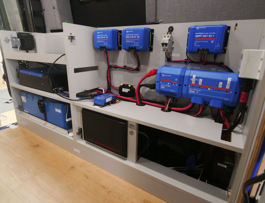
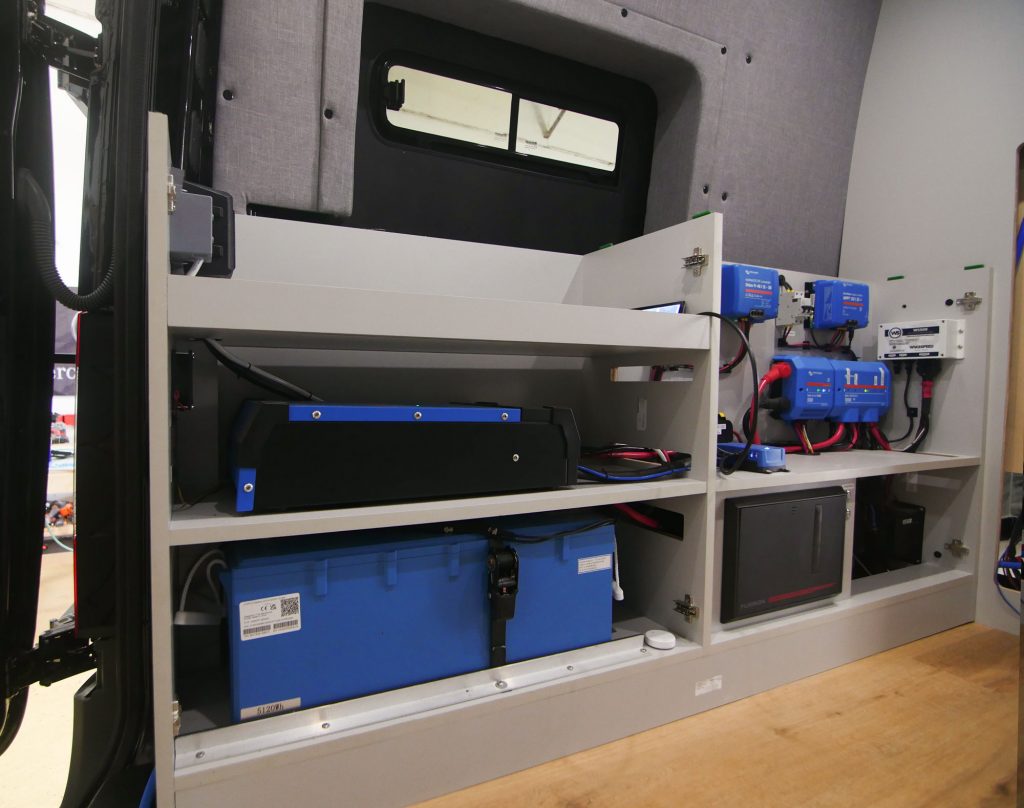
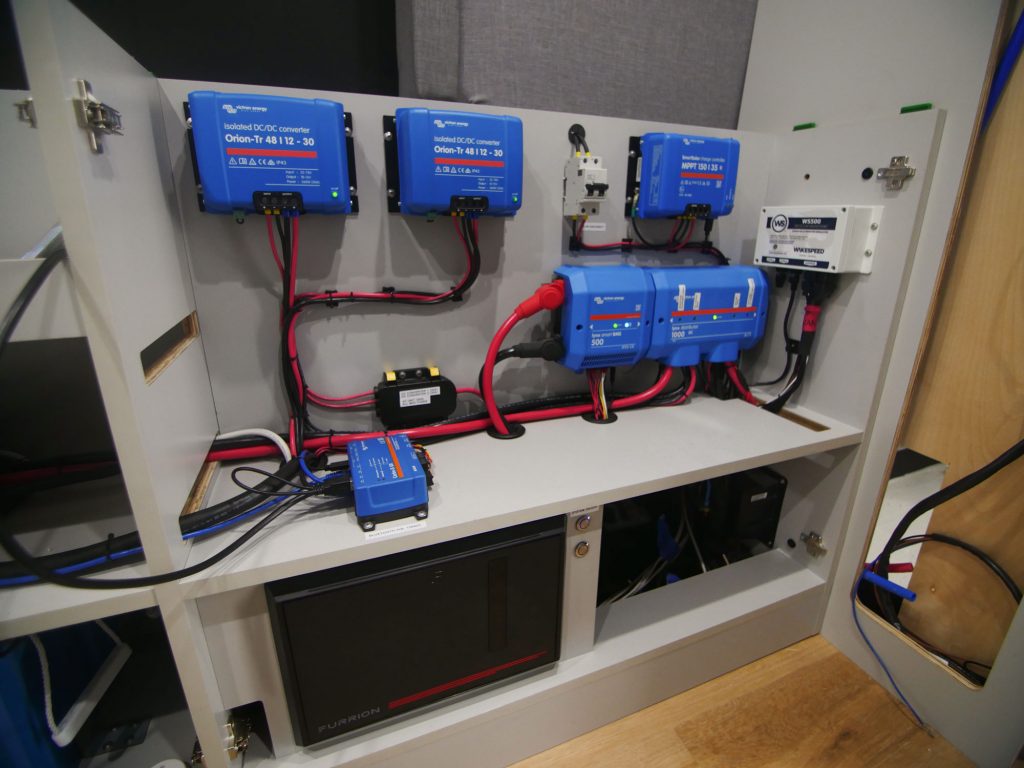
System Overview
If you download the wiring diagram as a PDF (link at top of the post), you can zoom in/out to see all the details presented there. In addition to the Nations/Wakespeed combo, this example system is full of brilliant blue boxes from Victron Energy!
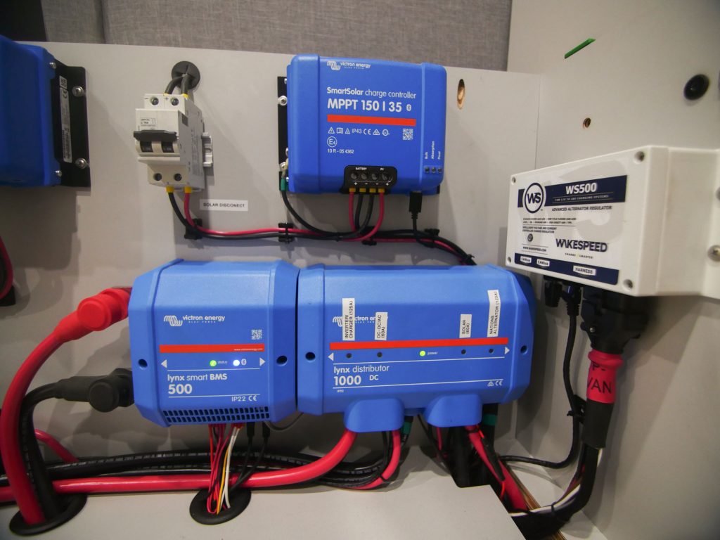
We offer the system with 2x (or more) Victron 100 amp hour, 48-volt (51.2 nominal voltage) Smart Lithium NG batteries wired in parallel using the Victron Lynx Class-T Power In (M10). That is roughly equivalent to an 800 amp hour battery bank at 12-volts. These are “external-BMS” batteries which means that the Battery Management System is not inside each battery like many lithium batteries such as Battleborn or SOK, etc. Instead, this system uses the Lynx Smart BMS NG for both batteries (or more if you were to add additional in the future). The Lynx Smart BMS is a combination of a BMS, a system-wide battery monitoring shunt/monitor, and a giant disconnect switch (more on that later) that is integrated into the Lynx system from Victron including the single Lynx Distributor (M10) we have in this system. You can read more about internal vs. external BMS batteries in this post.
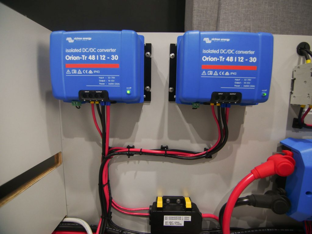
The rest of the system is fairly typical for a van/RV/mobile power system (MultiPlus inverter/charger, solar controller, etc.) except that things are running at 48-volt instead of a more traditional 12-volt. We also need a pair of Orion 48/12/30 DC-DC converters running in parallel to convert the 48-volts DC to 12-volts DC to supply power to all the normal 12-volt stuff (lights, refrigerator, etc.).
Battery Notes
The example system and best price product bundle use 2x (or more) Victron 100 amp hour, 48-volt (51.2 nominal voltage) Smart Lithium NG batteries. When it comes to batteries, most people are pretty focused and familiar with two key specifications: voltage (48-volts in this case) and the storage capacity, typically expressed in amp hours (100Ah per battery in this case resulting in 200+ amp hours when wired into a bank in parallel). The other key specifications are the “recommended charge current” (≤100A for these batteries) and the “recommended discharge current” (≤100 amps for these batteries). Those last two are basically how quickly you can refill the batteries when charging or how quickly you can discharge them for your loads. If your chargers or loads are higher than those ratings, you can damage the batteries or create excessive heat. External BMS batteries like these typically have much better specifications since, often, an internal BMS is the limiting factor. You can see all the specifications of the batteries here.
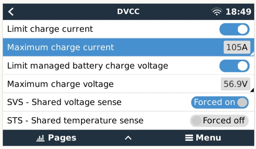
So, if there is any limitation at all in the example system, which is a strange thing to write in the context of this massive beast of a power system, it’s that you might find yourself in a rare and unusual situation where the combination of your off-grid charging sources (secondary alternator and solar) may actually exceed the recommended charge current rating of the battery bank. In the example system (with two batteries), this is 200 amps (100 amps per battery) which at the nominal voltage of 51.2 volts is 10,240 watts! So, that’s a lot of juice for being a “limitation”. Another great feature of this system is that it will automatically coordinate the maximum allowed charging current across all the charging sources using something called DVCC (Distributed Voltage and Current Control). This is possible because every charger in this system has digital connectivity to the Cerbo GX (Wakespeed regulating the Nations alternator via VE.Can, solar charge controller via VE.Direct and the MultiPlus inverter/charger via VE.Bus) and the Cerbo GX is communicating with the BMS and its current monitoring shunt via VE.Can as well. In the Cerbo GX we can set a “maximum charge current” and have it intelligently manage this for us. So, in those “perfect” conditions you’re going to keep the batteries happy but in some cases, forfeit some of potential power available at that moment by throttling down one or more charging source. Below is this setting in the Cerbo GX (Menu -> Settings -> DVCC).
Since you have plenty of “headroom” on the maximum charge current, it’s even possible to charge from the standard, vehicle alternator with this 12-volt to 48-volt battery to battery (DC-DC charger) from Sterling Power that could be added to the system so that you could charge from BOTH your Nations secondary alternator as well as your factory vehicle/alternator or use that unit as a sort of backup.
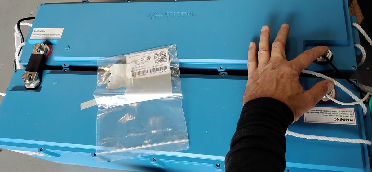
Victron recommends that you update the firmware of new batteries (using VictronConnect and Bluetooth) and pre-charge your batteries individually before wiring them up into a system. Full details in the manual.
And, if you’re wondering, you don’t feel like you’re getting shocked if you touch the 48-volt terminals of the battery. Here I am demonstrating this and I feel fine 🙂
But, Where Is The Main Disconnect?
Missing the bulky red disconnect/battery switch you’re probably used to seeing bolted onto a Lynx Distributor? This system uses the Victron Energy Lynx Smart BMS NG which has one of those massive switches built into it. It’s a 500 amp rated “contactor” that can open or close to act as a switch being “on” or “off” respectively. As the name suggests, it’s also the BMS (Battery Management System) for our Victron Smart Batteries so, if the batteries are distressed (too hot, too cold, over or under voltage), they can trigger this contactor to “open” which will electrically disconnect all the “loads and chargers” connected downstream from the Lynx Smart BMS electrically. Finally, there is also a battery monitoring shunt inside the Lynx Smart BMS that communicates with the Cerbo GX to show the same kind of battery status information that the popular BMV-712 does. All this in one single box! But that’s not all! If you look closely at the example wiring diagram, you’ll see that we have a toggle switch wired into the “remote” terminals on the Lynx Smart BMS. This allows you to open/close the contactor (turn off/on the system) with that switch in the same way you would a big, bulky main disconnect switch with one HUGE advantage. Anytime the contactor in the Lynx Smart BMS is about to open – whether triggered by the batteries to protect themselves – or by you manually – the BMS will communicate this to the Wakespeed WS500 regulator before this happens so that the alternator can stop producing charging current thus preventing an extremely dangerous voltage spike that would occur if someone flipped off a manual disconnect switch while the alternator was charging! More about so-called “load dumps” earlier in this post.
Field Drive in 48-Volt Alternator Systems
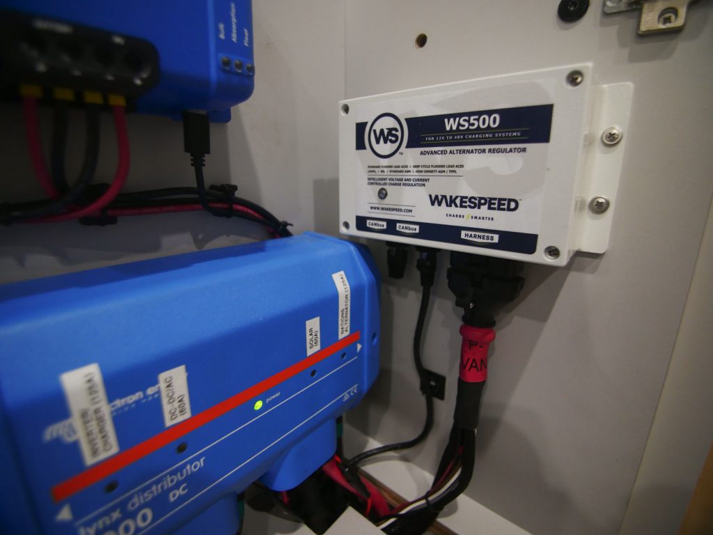
First, what is the field drive? It’s the wire that supplies voltage to the alternator’s rotating field coil. In this example system, it’s the blue wire on the Wakespeed wiring harness “alternator leg”. You can think of the field drive as the sort of gas pedal – the more field voltage, the more current the alternator will produce. If you want to dive deeper into how alternators work, this is a pretty good video.
We often get asked if you can install a secondary alternator onto an engine before you finish the rest of the electrical system and wire it up to that system. The answer is yes! Even though the alternator will be spinning after the mechanical installation, it won’t be producing any current until the Wakespeed regulator gets installed and provides the field voltage to the alternator.
In 12-volt and 24-volt systems it’s common for the “field” to be specified to operate at the same voltage as the connected battery. This is not always the case with 48-volt alternators. In fact, many 48-volt alternators, the field is actually specified at 12-volt. In such cases, there are a couple of ways the Wakespeed WS500 can be deployed.
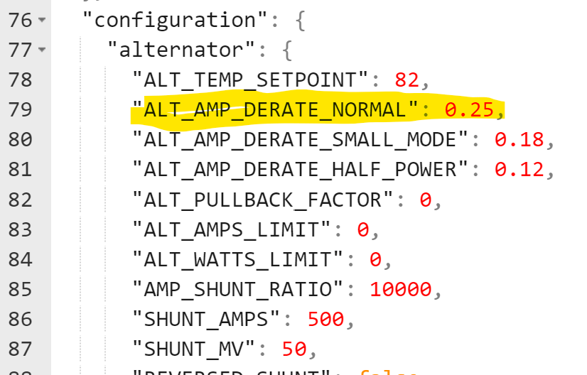
- This is what we recommend… Apply a derate value using the $SCA command when configuring your Wakespeed. The $SCA command has three ‘”derate” values which can be set to “normal”, “small alt”, and “half-power”. These are typically used to reduce the output of an alternator to account for system cooling concerns and prevent overheating and/or to reduce the load on the driving engine. But they can also be used to effectively reduce the “field voltage” from 48-volt to allow direct driving of a 12-volt field alternator even when the red, power supply wire on the Wakespeed harness (ALT+) is attached to a 48-volt battery system. To do this simply start with a “normal’ derate value of 0.25 (25%) which will reduce the average field voltage to an acceptable operation range. Due to the prevalence of 12-volt fields in 48-volt alternators, beginning with version 2.5.0 of the Wakespeed firmware, it will default to this 25% derate values if those have not been explicitly defined using the $SCO command detailed above. If your alternator has a true 48-volt field (the Nations alternator we show in this example system uses a 12-volt field), you will want to explicitly issue a $SCO command to restore the 100% field drive (r max field drive is otherwise appropriate).
- Connect the red, power supply wire on the Wakespeed harness (ALT+) to a 12-volt source such as the vehicle battery. Importantly, if you take this approach, you need to be sure to wire the red/yellow wire (VBAT+) from the Wakespeed harness to the 48-volt battery for proper voltage sensing. This does not work with the “van harness” which is a simplified version of the “standard” Wakespeed harness that does not include the VBAT+ wire.
Circuit Protection
In our example wiring diagram (zoom in on the PDF), we’re using the Lynx Smart BMS with a Lynx Distributor downstream as the main bus bar. From left to right, we show the following connections and fusing:
- 125A (80V) mega fuse for the Nations alternator charging output
- 125A (80V) mega fuse for the MultiPlus inverter/charger
- 80A (80V) mega fuse to feed the Littelfuse secondary bus bar that accepts lower current rated, MIDI fuses (see below)
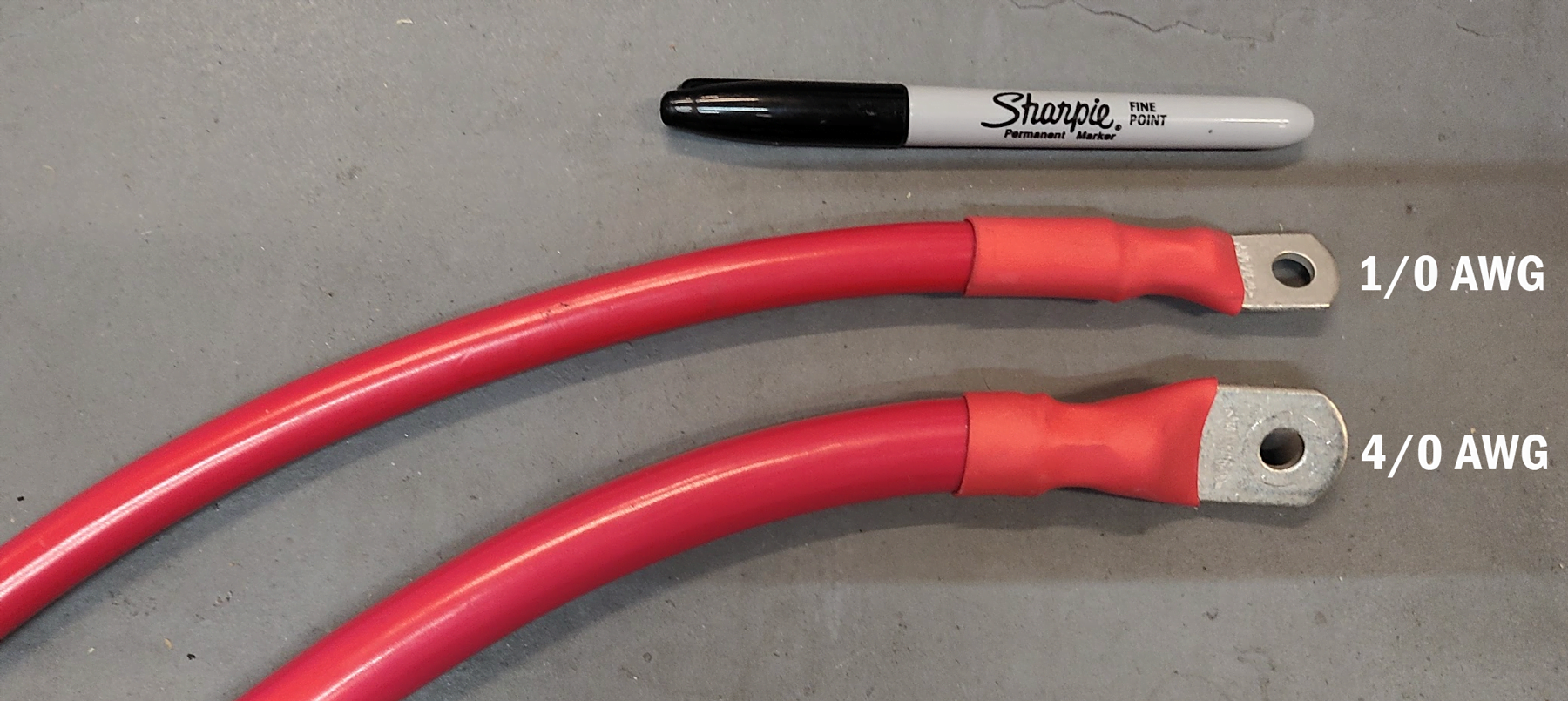
- 60A (80V) mega fuse for the charging output of the solar charge controller. Note that this fuse size is larger than it needs to be (max of 35 amps from the charge controller multiplied by 1.25 (25% additional) is around 44 amps. However, the 10 AWG wire we show can accept 60 amps at 48-volts, so we can have this additional headroom. Remember that circuit protection is to ensure your wires are not exceeding their maximum ampacity.
The example wiring diagram uses a very compact, Littelfuse bus bar with MIDI fuses. as a secondary bus bar. It’s kind of like a miniature Lynx Distributor in the sense that it combines a bus bar with fusing. However, it does not have a negative bus bar so any required negative wiring is run to the main bus bar (Lynx Distributor). Ideally, you keep your wire lengths for the positive and negative wires close to the same lengths. There are the following three connection points inside the secondary bus bar.
- 30A (58V) MIDI fuse for one of the two Orion 48/12/30 converters. Similar to the 60 amp fuse above, this is larger than the load requires but the lowest amp-rated MIDI fuse from Victron. The Orions will pull about 6-8 amps to create the 360 watts at 12 volts. But, here again, the 10 AWG wire is more than capable of carrying up to 60 amps if there was something like a short circuit.
- 30A (58V) MIDI fuse for the second of the two Orion 48/12/30 converters
- 50A (58V) MIDI fuse for an additional 48-volt appliance such as an air conditioner. In our example, we’d be using a Nomadic Cooling X3 which calls for a 50 amp fuse (see specifications chart).
Configuration
With everything wired up, let’s dive into configuring the system! Given the nature of this post, we’re only going to focus on the configuration steps for enabling the secondary alternator and Wakespeed regulator. One awesome feature of this system provided with the Lynx Smart BMS is that the charge profile for the other Victron Energy chargers in our example system (MultiPlus inverter/charger and solar charge controller) is managed intelligently by the Cerbo GX using DVCC. This is possible because all of these devices are “talking” to each other digitally through the Cerbo GX. If you want to learn more about this DVCC magic you can read this section of the Cerbo GX manual. One benefit of this is that it’s quite easy to configure the system for charging. But, If your system has other chargers/devices that don’t have a data connection on them (no VE.Bus, VE.Direct, VE.Can, etc.), such as an older (pre-Orion XS) Orion DC-DC charger, and therefore cannot be managed by DVCC, you’ll have to configure that device the “old fashioned” way with VictronConnect which is beyond the scope of this post.
We also won’t discuss all the setup possibilities of the Cerbo GX – you can check out this other post about that. Instead, we’ll only focus on what’s necessary to make it work with the Wakespeed regulator. However, we’ll be dedicating another post to the Cerbo GX including connecting it to VRM so “stay tuned” for that, or consider signing up for our email newsletter which is available at the bottom of all of our pages.
Victron Lynx Smart BMS Configuration with Victron Connect
Remember that any Victron product with the word Smart in the name means that you can configure, monitor, and control it via Bluetooth using the VictronConnect app. So, if you haven’t done so already, you’ll want to install VictronConnect. Links to download the app are available for iOS, Android, Windows, or MacOS on the VictronConnect page. Most folks find the app simple to use but you can read through the manual if you need it. To use it, you’ll need Bluetooth enabled on your mobile device or computer so that it can communicate with the various Victron products. Once you open the app, you’ll see a list of all the Victron products that are within Bluetooth range -all with their factory default names. You can easily rename each device to make it unique to your install if you’d like.
To configure (or monitor/control) a device simply click on its name from the list in VictronConnect. The first time you connect you’ll be asked to pair with that device. The default pairing PIN is 000000. We recommend you change the PIN on all your devices so that other users of VictronConnect don’t mess with your system! Keep in mind that if you find yourself in a place with other camper vans/RVs that have Victron components you might see a bunch of other devices listed in VictronConnect – basically anything that’s within Bluetooth range.
By the way, if you don’t have any of this equipment yet but are curious how it all works, you can actually use VictronConnect with “virtual” (demo) devices. In other words, you can go through the settings and screens available in VictronConnect for any Victron Smart product by using the demo library available in VictronConnect. This is a great feature to use when planning a system.
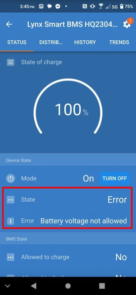
Let’s start with the Lynx Smart BMS NG. Connect to this device in VictronConnect. The first screen you’ll see is the “status” tab that displays the same kind of information as other battery monitors from Victron including the calculated state of charge (SOC) as a percentage and if you scroll down, a bunch of other information about the battery including voltage, current, etc. Below is a screenshot of this screen.
Since the Lynx BMS is configured for 12-volt batteries by default, the first thing you’ll notice is an error reading “battery voltage not allowed”. You are likely to be prompted for a firmware update as well. If so, proceed with that firmware upgrade.
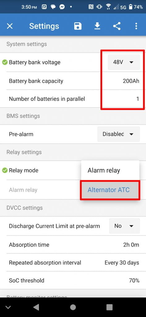
Next, enter the settings of the Lynx Smart BMS NG by tapping on the “gear icon” in the very top right part of the screen. Here you’ll want to change the system voltage to 48 and tell the BMS about your batteries. In our base system with the 2x, 100Ah batteries in parallel you would enter 2x for batteries and 200 amp hours for campacity. You’ll also want to change the “relay mode” setting to “alternator ATC”. This is how the “white wire” (feature in wire) that we wired from the Wakespeed harness into terminal #9 on the multi-connector of the Lynx SmartBMS is interpreted by the BMS. It enables the ATC (allow to charge) relay to disable charging from the Wakespeed/Nations if the battery triggers that state.
Note: if you’ve ever configured another Victron Energy battery monitor such as the BMV-712 or SmartShunt you may notice that the settings presented here are different and, in some ways, more simple than you’d see on the other products. That’s because, in this example system, you can literally only use one single type of battery – a Victron Smart lithium battery. The batteries may have different capacities (200 vs. 300Ah, etc.) but they are the same baseline so many of the settings about the battery that you have to change/set in other systems are already known/assumed in this case.
Wakespeed WS500 Configuration
If you buy your Wakespeed regulator from us as part of our best price product bundle for this system it will ship pre-configured based on the information we collect when you add the stuff to your cart.
However, configuring a Wakespeed WS500 regulator is pretty simple when using the Wakespeed Android app – particularly with the latest Wakespeed Pro that we stock that has a Bluetooth connection.
Configuring the Orion 48/12/30 DC-DC Converters
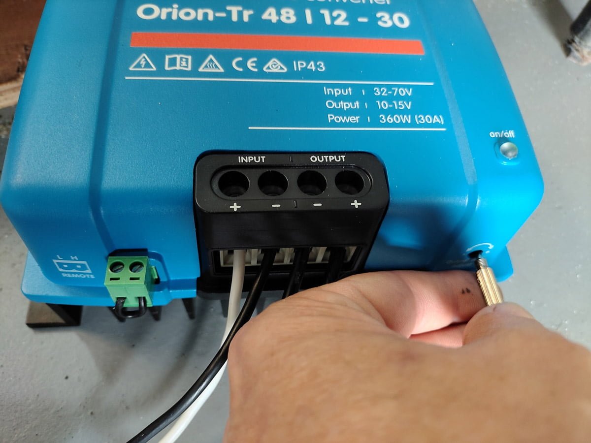
These are the devices that convert the 48-volt system voltage to 12-volts for your main DC load center for your common 12-volt stuff like lights, fans, appliances, etc. They are not “Smart” so there is no Bluetooth connection for configuration/monitoring. But they’re quite simple devices. All you’re going to do with these is get a tiny screwdriver and turn the potentiometer (how often do you get to use that word!) to adjust the output voltage (-15% to +25% of the default output voltage). Turn counterclockwise to decrease the output voltage. Turn clockwise to increase the output voltage. In our system, we’re setting this to right around 13.5 volts which is a typical “float voltage” in a 12-volt system.
Charts! Nations Alternator Charging Output Comparisons (12V / 24 / 48V)
Click On Images To Open Larger
Other Recommend Reading/Resources
- This video details every connection on the Wakespeed WS500 van harness.
- There is a lot of relevant additional information in our blog post about the 12-volt version of this system that we didn’t want to repeat here.
- We’ve always used the Blue Sea Circuit Wizard for sizing wires in 12-volts but it doesn’t work for 48-volt systems. However, we found this 48-volt wire size calculator to be very useful. There are quite a few configuration options.
- Blog post about configuring a Cerbo GX and Lynx Shunt for battery monitoring.
- If you have a Sprinter and want to remotely start it at a specified battery state of charge (SOC) and/or have it idle up to produce more RPMs/alternator charging current check out this kit from Mid City Engineering.
- A quick note on Mercedes Sprinter N62 bracket: The general consensus (Nations, our installers, reports from the internet) is that the 3-belt system that is used by Nations in their kits for Sprinters without the N62 “factory secondary alternator bracket” are better than the N62 version. In fact, we’ve heard of reports from Nations that some people who paid at the dealership for the N62 bracket have taken it off in favor of the 3-belt option.
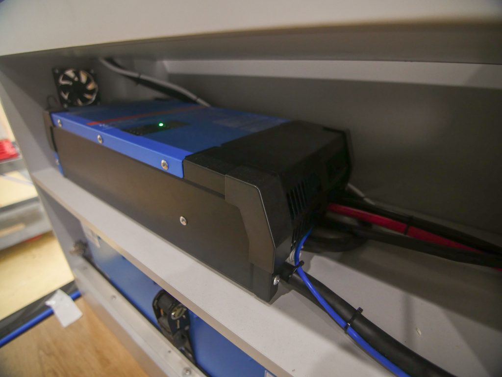
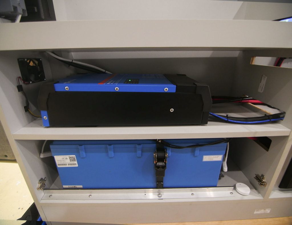
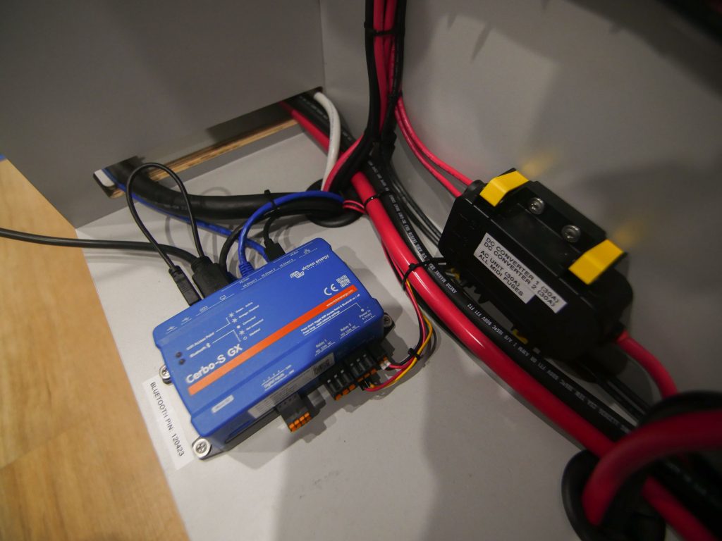
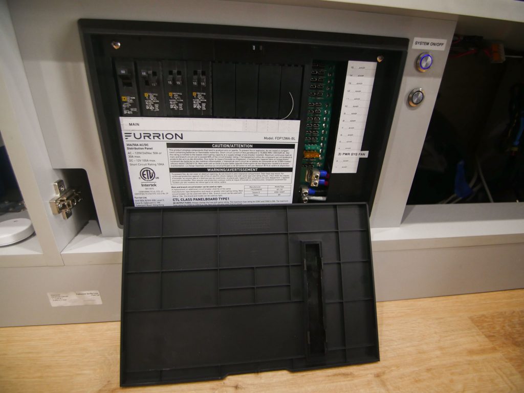
Installation Photos and Testing Results
Note, these tests were were done with the older/original configuration of this system using 2x, 24-volt batteries wired in series as we detail at the beginning of this blog post. However, what we’re testing is really the performance of the Nations alternator with the Wakespeed regulator which will be the same with the newer, 48-volt Smart Lithium NG batteries.